Supercharge Your Innovation With Domain-Expert AI Agents!

Optical pickup device and optical disk device and optical device and composite optical element

a pickup device and optical disk technology, applied in the direction of data recording, instruments, disposition/mounting of heads, etc., can solve the problem that the focusing error signal fe cannot be appropriately provided in the optical pickup device, and achieve the effect of reliable focusing error signal

Inactive Publication Date: 2005-04-28
SONY CORP
View PDF8 Cites 8 Cited by
  • Summary
  • Abstract
  • Description
  • Claims
  • Application Information

AI Technical Summary

Benefits of technology

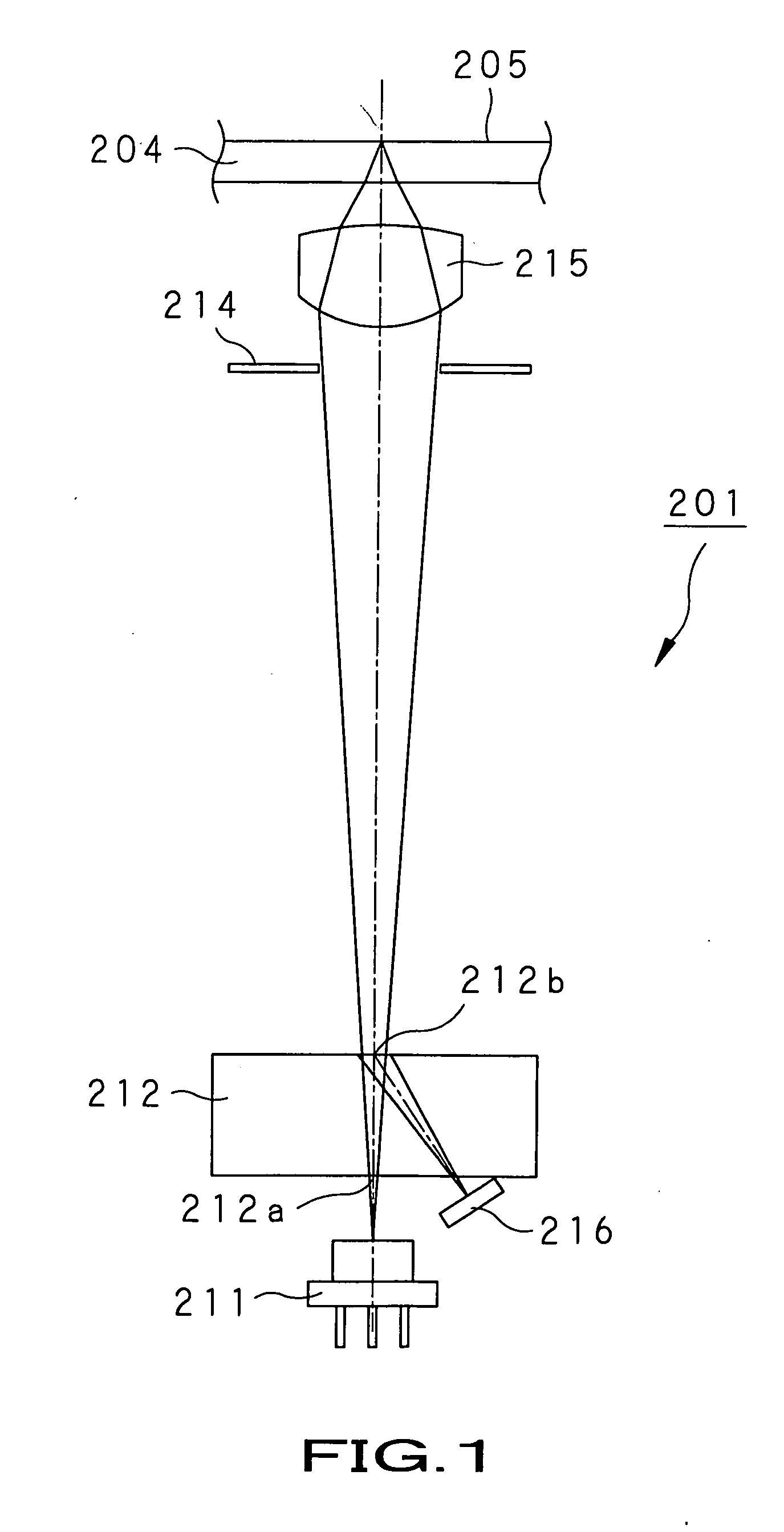
The present invention provides an optical pickup device and optical disk drive that can improve the focusing error signal by directing the return light from the optical disk to a specific position on the light-detecting means. This is achieved by using a composite optical element that includes a diffraction element and a light-path deviation correcting means to correct astigmatism caused by variations in wavelength of the light beam emitted from the light source. The optical pickup device and optical disk drive can also prevent deformation of the return light caused by astigmatism in the optical system. These improvements can lead to a more reliable focusing error signal and better performance of the optical pickup device and optical disk drive.

Problems solved by technology

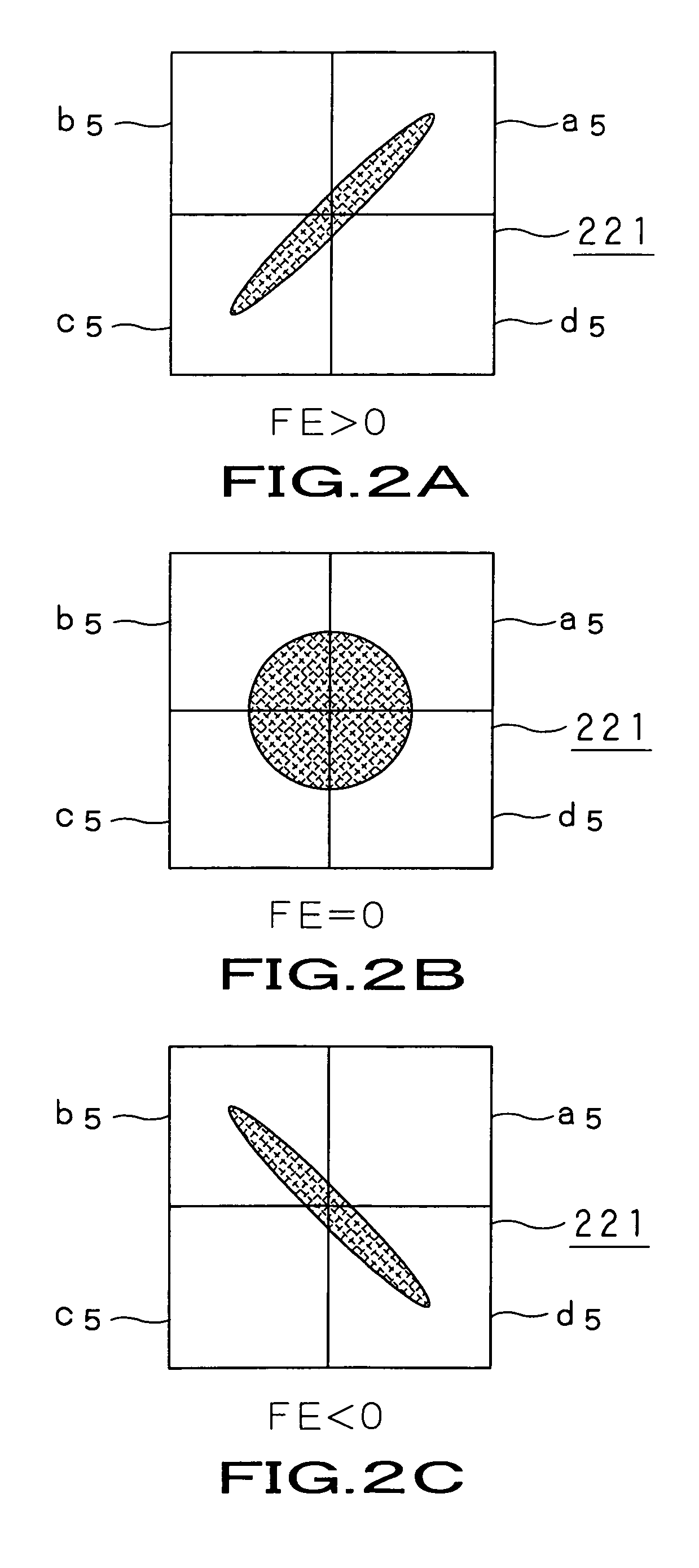
Also in this case, any focusing error signal FE cannot appropriately be provided in the optical pickup device.

Method used


Image

  • Optical pickup device and optical disk device and optical device and composite optical element
  • Optical pickup device and optical disk device and optical device and composite optical element
  • Optical pickup device and optical disk device and optical device and composite optical element

Examples


Embodiment Construction

[0108] The present invention will be described in detail concerning the optical disk drive as an embodiment thereof with reference to the accompanying drawings.

[0109]FIG. 4 schematically illustrates the optical disk drive according to the present invention in a block diagram form. The optical disk drive is generally indicated with a reference 1. The optical disk drive 1 writes and reads information to and from an optical disk 2 such as CD (compact disk), DVD (digital versatile disk), CD-R (recordable CD), CD-RW (rewritable CD), magneto-optical disk or the like.

[0110] According to the present invention, the optical disk drive 1 includes an optical pickup 3 that writes and reads information to and from the optical disk 2, a disk rotation driving mechanism 4 that drives to rotate the optical disk 2, a feeding mechanism 5 that moves the optical pickup 3 radially with respect to the optical disk 2, and a controller 6 that controls the optical pickup 3, disk rotation driving mechanism 4...


PUM

PropertyMeasurementUnit
angleaaaaaaaaaa
wavelengthaaaaaaaaaa

Abstract

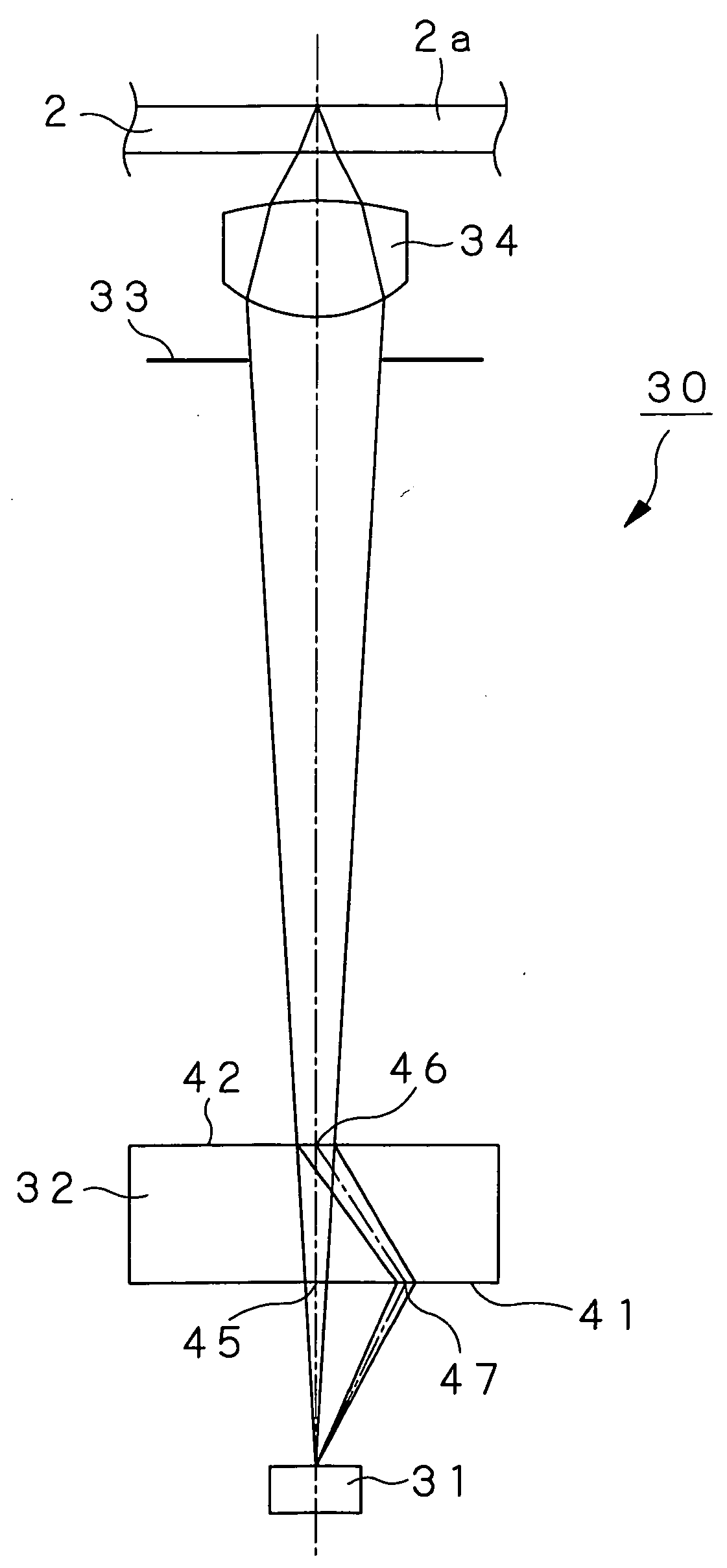
An optical pickup device is provided which includes a first diffraction grating (45) that splits a light beam emitted from a light-emitting / -detecting element (31) into a zero-order light beam and positive and negative first-order light beams, a second diffraction grating (46) that diffracts return light from an optical disk (2) for traveling along a light path separate from that of the outgoing light, and a third diffraction grating (47) that corrects the deviation of the light path by diffracting the positive first-order light beam diffracted by the second diffraction grating (46). The light-emitting / -detecting element (31) provides a focusing error signal FE by detecting the negative first-order light beam, and a tracking error signal by detecting return portions of the positive and negative first-order light beams from the first diffraction grating (45).

Description

TECHNICAL FIELD [0001] The present invention relates to an optical pickup device used to write and read information optically to and from an optical disk to and from which information is optically written and read, such as magneto-optical disk, phase-change optical disk or the like, and an optical disk drive using the optical pickup device, and also to an optical device used in these optical pickup device and optical disk drive, and a composite optical element having the optical device formed integrally therein. [0002] This application claims the priority of the Japanese Patent Application No. 2001-358244 filed on Nov. 22, 2001, the entirety of which is incorporated by reference herein. BACKGROUND ART [0003] Conventionally, optical pickup devices are known that are used to write and read information optically to and from an optical disk to and from which information is optically written and read, such as magneto-optical disk, phase-change optical disk or the like. [0004] As a typica...

Claims


Application Information

Patent Timeline
Patent Type & Authority Applications(United States)
IPC IPC(8): G11B7/00G11B7/09G11B7/135
CPCG11B7/00G11B7/0901G11B7/0908G11B7/1381G11B7/0916G11B7/1356G11B7/0909G11B7/1359G11B7/1353G11B7/09
Inventor FUKASAWA, NORIOSUZUKI, JUNICHITOYOTA, KIYOSHITANAKA, TETSUKUBO, TAKESHISAITO, MASAHIROISHII, SATORU
Owner SONY CORP
Features
  • R&D
  • Intellectual Property
  • Life Sciences
  • Materials
  • Tech Scout
  • Unparalleled Data Quality
  • Higher Quality Content
  • 60% Fewer Hallucinations
Learn More