Multi-channel audio surround sound from front located loudspeakers

a loudspeaker and multi-channel technology, applied in the direction of stereophonic systems, stereophonic arrangments, electrical apparatus, etc., can solve the problems of complex frequency response pattern, difficult and costly production of phantom sound sources at specific locations, and complex frequency response components of hrtf's

Active Publication Date: 2005-04-28
POLK AUDIO LLC
View PDF4 Cites 111 Cited by
  • Summary
  • Abstract
  • Description
  • Claims
  • Application Information

AI Technical Summary

Benefits of technology

[0015] Therefore, it is an object of this invention to provide a device and method for producing phantom rear surround sound channels or a phantom surround sound effect from a loudspeaker system or pair of loudspeaker systems located in front of the listener. An additional object of this invention is to permit implementation using simple analog filters or simple DSP. It is another object of the present invention to be more tolerant of loudspeaker characteristics, loudspeaker placement, listener location and listener to listener variation. Yet another object of this invention is to create effective surround sound reproduction when using commonly available audio surround sound recordings. A further object of this invention is to generate phantom sound sources that are perceived as originating from a range of different locations around or behind the listener including the general areas directly to the left and right of the listener.
[0017] In accordance with one embodiment of the present invention, in an audio reproduction system having at least four inputs for accepting at least four audio input signals, for example, left front, right front, left surround and right surround channel signals, a right main speaker and a left main speaker are provided respectively at right and left main speaker locations along a speaker axis which are equidistantly spaced from the principle listening location. The principle listening location LL is generally defined as a spatial position for accommodating a listener's head facing the main speakers along a central listening axis and having a right ear location and a left ear location along an ear axis, with the right and left ear locations separated by a maximum interaural sound distance of Δtmax and the principle listening location is specifically defined as the point on the ear axis equidistant to the right and left ears. The central listening axis CLA is defined as a line passing through the principle listening location and a point on the speaker axis equidistant from the right and left main speakers. A right sub-speaker and a left sub-speaker are provided at right and left sub-speaker locations substantially on the speaker axis of the left and right main speakers and which are equidistantly spaced from the principle listening location LL. By careful location of the sub-speakers relative to the main speakers, use of proper modifications and combinations of the left and right surround signals to create driving signals for the main and sub-speakers, and appropriate filtering of the component parts of said driving signals, a listener located in the principle listening location LL perceives a surround sound experience from speakers located only in front of the listener.

Problems solved by technology

However, until the availability of inexpensive, powerful digital signal processing (DSP) more accurate generation of phantom sound sources at specific locations was very difficult and costly due to the complexity of accurate HRTF synthesis.
In addition, sounds arriving from a particular direction produce a complicated frequency response pattern at each ear which is characteristic of that specific directional location.
The frequency response component of the HRTF's is quite complex and somewhat different for each individual.
In general, methods using HRTF's to create phantom sound sources, whether for simulation of a surround sound audio system or other application, have a number of practical limitations.
Accurate representation of HRTF's is very computation intensive and it is therefore difficult to obtain sufficient accuracy using practical and cost efficient DSP methods.
Given the highly specific and detailed nature of HRTF's, those skilled in the art will recognize that changes in the loudspeaker characteristics or locations combined with movement of the listener away from the assumed listening location can easily destroy the phantom sound source illusion.
Also, the actual HRTF's of some listeners may be too different from the HRTF's employed
These methods may be subject to the above described limitations and will also function properly only when using input signals made with the specified recording scheme.
Furthermore, as will be understood by those skilled in the art, audio surround sound systems composed of front and rear pairs of speakers are not effective in localizing sounds in the general areas

Method used


Image

  • Multi-channel audio surround sound from front located loudspeakers
  • Multi-channel audio surround sound from front located loudspeakers
  • Multi-channel audio surround sound from front located loudspeakers

Examples


first embodiment

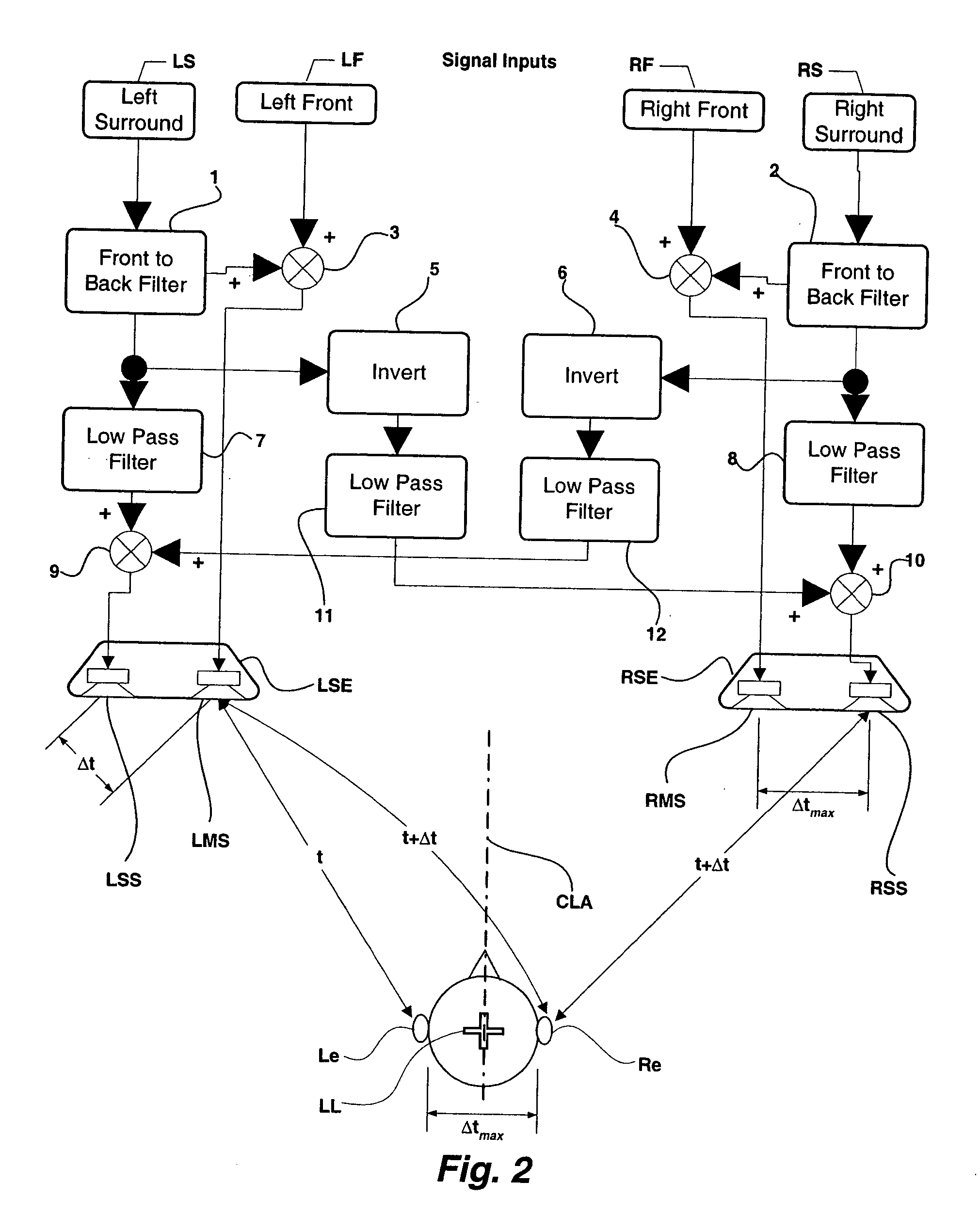
[0050] Therefore, in this first embodiment the front-to-back filters 1 and 2 of FIG. 2 may have characteristics which limit the frequency range to below approximately 2,500 Hz and which have approximately the frequency response of the curve labeled “45-135 deg.” in FIG. 4 for frequencies below approximately 2,500 Hz. As noted above and as shown in FIG. 6, because front-to-back frequency response curves are very similar below approximately 2,500 Hz over a range of angular locations and for both near and farthest ear, even if the speakers are not located at exactly 45 degrees from the central listening axis CLA, the front-to-back filters 1 and 2 will still cause the listener to perceive that sounds,are coming from mirror image locations behind the listener, as shown in FIG. 7. Notwithstanding the foregoing discussion, experiments have shown that in some implementations of the present invention it is desirable for the frequency response of front-to-back filters 1 and 2 to extend substa...

second embodiment

[0056]FIG. 9 shows a family of curves calculated by subtracting the frequency response shown in FIG. 3 for sounds arriving from a particular direction at the listener's nearest ear from the frequency response for sounds arriving from the same direction at the listener's farthest ear. Therefore, these curves represent the change in frequency response of a sound as it passes across the listener's head from left to right or right to left. By inspection of FIG. 9 it can be seen that these curves are similar in shape and magnitude up to a frequency of approximately 2,000 Hz. Referring again to this second embodiment of the present invention as shown in FIG.10, left-right filter 13 may have approximately the characteristics of, for example, the curve of FIG. 9 labeled, “45 to −45”. Thus, the inverted and low-passed left surround signal produced by right sub-speaker RSS for the purpose of canceling IAC will better match the frequency response of the in-phase left surround signal produced b...

fifth embodiment

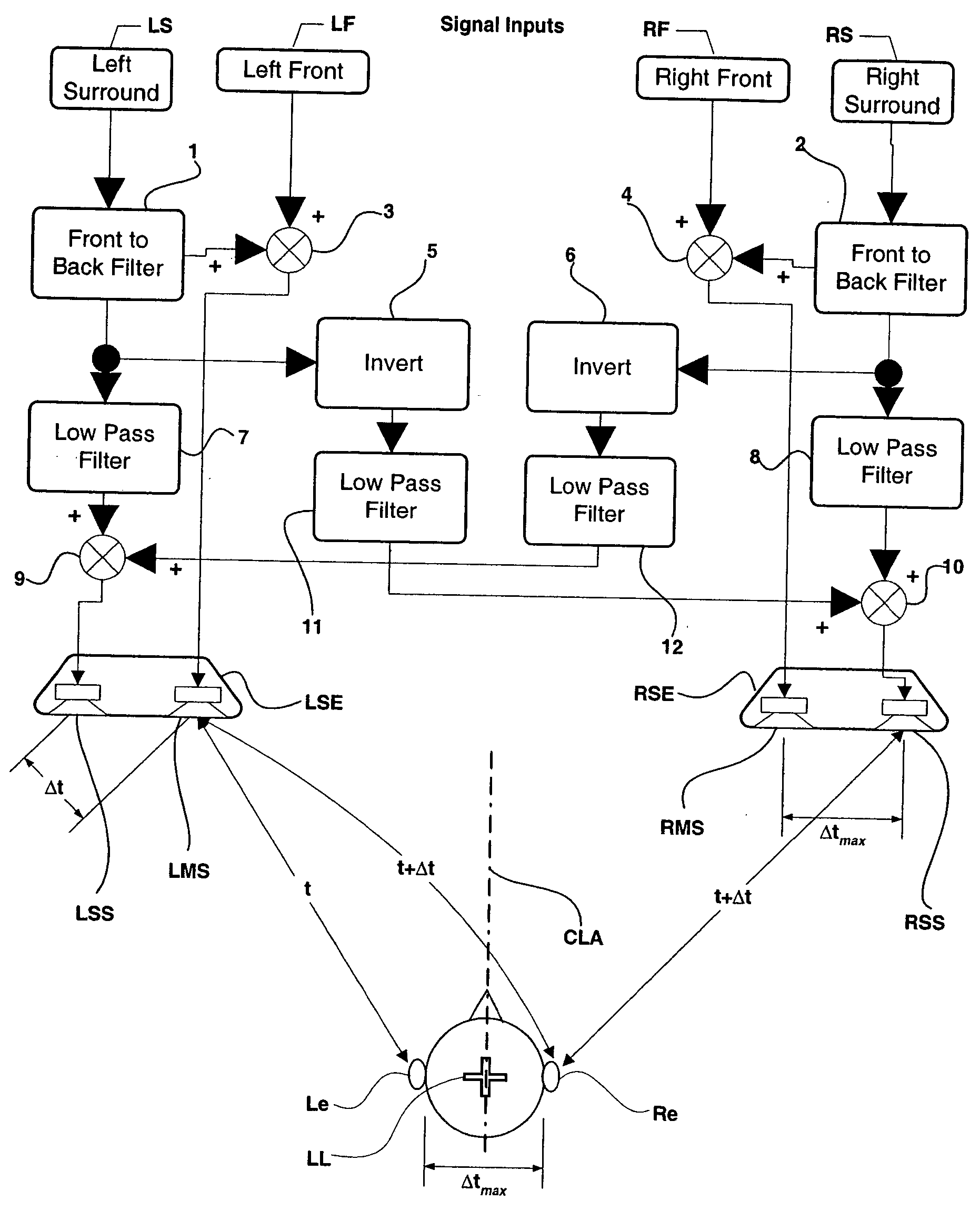
[0059] the present invention is shown in FIG. 13 and FIG. 13a. This embodiment of the present invention is similar to the first embodiment described with respect to FIG. 2, except that left and right front signals LF and RF are applied to the left and right sub speakers LSS and RSS through certain filters and signal manipulations so as to cancel IAC and create an expanded range of perceived front sound locations in addition to the perceived range of rear sound locations previously discussed in the first embodiment. Referring to FIG. 13, left front signal LF is combined with left surround signal LS by adder 3 after left surround signal LS has been modified by front-to-back filter 1. Similarly, right front signal RF is combined with right surround signal RS by adder 4 after right surround signal RS has been modified by front-to-back filter 2. The combination of left front signal LF and modified left surround signal LS is transmitted to left main speaker LMS and is also subtracted from...


PUM


Abstract

A surround sound reproduction system uses a series of filters and a system of main and sub-speakers to produce phantom rear surround sound channels or a phantom surround sound effect from a loudspeaker system or pair of loudspeaker systems located in front of the listener. The sound system includes left and right surround input signals, and left and right front input signals. Left and right sub-speakers, and left and right main speakers are located in front of a listening location. Spacing between respective main and sub-speakers is approximately equal to ear spacing for an average person. The input to the left sub-speaker comprises the right surround signal subtracted from the left surround signal each signal having previously passed through a front-to-back filter and a series of high and low pass filters. The input into the left main speaker comprises the left front signal added to the left surround signal after the left surround signal has passed through a front-to-back filter. The input into the right sub-speaker comprises the left surround signal subtracted from the right surround signal each signal having previously passed through a front-to-back filter and a series of high and low pass filters. The input into the right main speaker comprises the right front signal added to the right surround signal after the right surround signal has passed through a front-to-back filter.

Description

BACKGROUND OF THE INVENTION [0001] 1. Field of the Invention [0002] This invention relates generally to the reproduction of sound in multichannel systems generically known as “surround-sound” systems and more specifically to the application of psychoacoustic principles in the design of a loudspeaker system for reproducing a surround sound experience from loudspeakers located only in front of the listener. [0003] 2. Background Art [0004] It has long been recognized that it is possible to use interaural crosstalk cancellation (IACC) and head related transfer functions (HRTF) to expand the perceived soundstage of a two channel audio system or to create the illusion of sounds coming from phantom locations independent of the actual location of the loudspeakers. Through the 1970's and 1980's a number of audio components were available for purchase which used IACC to expand the perceived soundstage. However, until the availability of inexpensive, powerful digital signal processing (DSP) mo...

Claims


Application Information

Patent Timeline
Patent Type & Authority Applications(United States)
IPC IPC(8): H04R5/00H04R5/02H04S3/00
CPCH04S3/002H04R5/02
Inventor POLK, MATTHEW S. JR.
Owner POLK AUDIO LLC
Why Eureka
Try Eureka