Color-converting filter and manufacturing method

a technology of color-converting filters and manufacturing methods, which is applied in the direction of identification means, natural mineral layered products, instruments, etc., can solve the problems of pattern shape reproducibility and pattern deformation during subsequent manufacturing steps, drop in efficiency due to so-called concentration quenching, and decomposition of color-converting colorants, so as to simplify the driving circuitry of light sources, shorten the manufacturing process, and reduce the effect of labor intensity

Active Publication Date: 2005-04-28
SHARP KK
View PDF4 Cites 24 Cited by
  • Summary
  • Abstract
  • Description
  • Claims
  • Application Information

AI Technical Summary

Benefits of technology

[0011] It is thus an object of the present invention to provide a simplified method of manufacturing a color-converting filter which still allows for highly detailed patterning.
[0016] As described above, according to the manufacturing method of the first or second embodiment of the present invention, highly detailed color-converting layers can be formed through self-alignment using color filter layers as masks. According to the present invention, the necessity of carrying out patterning of the color-converting layers through photolithography is eliminated, and hence the manufacturing process can be shortened. Furthermore, color-converting layers having increased thickness are formed integrally with a flattening layer, and hence even if color-converting layers having a width that is narrow compared with the thickness are formed, misshaping and so on of the color-converting layers can be suppressed. According to the method of the present invention, a color-converting filter that can be used in a microdisplay (e.g. a video camera viewfinder) can thus be manufactured.
[0017] Moreover, the color-converting-function-possessing color filter of the third embodiment of the present invention has special advantages as a color filter for display. With this embodiment, for light emitted by independently controllable light sources in positions corresponding to sub-pixels provided in a matrix shape, the hue is changed by the colorant layer to produce white light, which enters the color filter layers of the sub-pixels. Consequently, unlike the case where color-converting layers are provided corresponding to the colors of the respective sub-pixels, identical light enters each of the color filter layers of the various colors, and hence the necessity of considering the efficiency of color conversion for the color-converting layers of each of the colors when driving the light sources is eliminated, and thus the driving circuitry for the light sources can be simplified and hence the cost can be reduced. Furthermore, since each of the light sources arranged in the matrix shape can be driven under identical conditions, the problem of only light sources corresponding to a particular color deteriorating upon prolonged driving can be suppressed, and hence the color tone of the display can be maintained for a prolonged period.

Problems solved by technology

An important problem in terms of practical application to a color display is providing a color-converting filter that enables detailed color display, is stable in terms of color fidelity and so on over a prolonged period, and also has high color conversion efficiency.
However, if the concentration of the color-converting colorants is increased to increase the color conversion efficiency, then a drop in the efficiency due to so-called concentration quenching, and decomposition of the color-converting colorants over time and so on will occur.
However, when the width of each line in the pattern is smaller than the film thickness of the color-converting layers, the reproducibility of the pattern shape and deformation of the pattern during subsequent manufacturing steps become problems.
For example, when a full-color display is to be obtained, at least red, green and blue color-converting layers are required, and hence the manufacturing process requires many steps, and is complex.

Method used


Image

  • Color-converting filter and manufacturing method
  • Color-converting filter and manufacturing method
  • Color-converting filter and manufacturing method

Examples


example 1

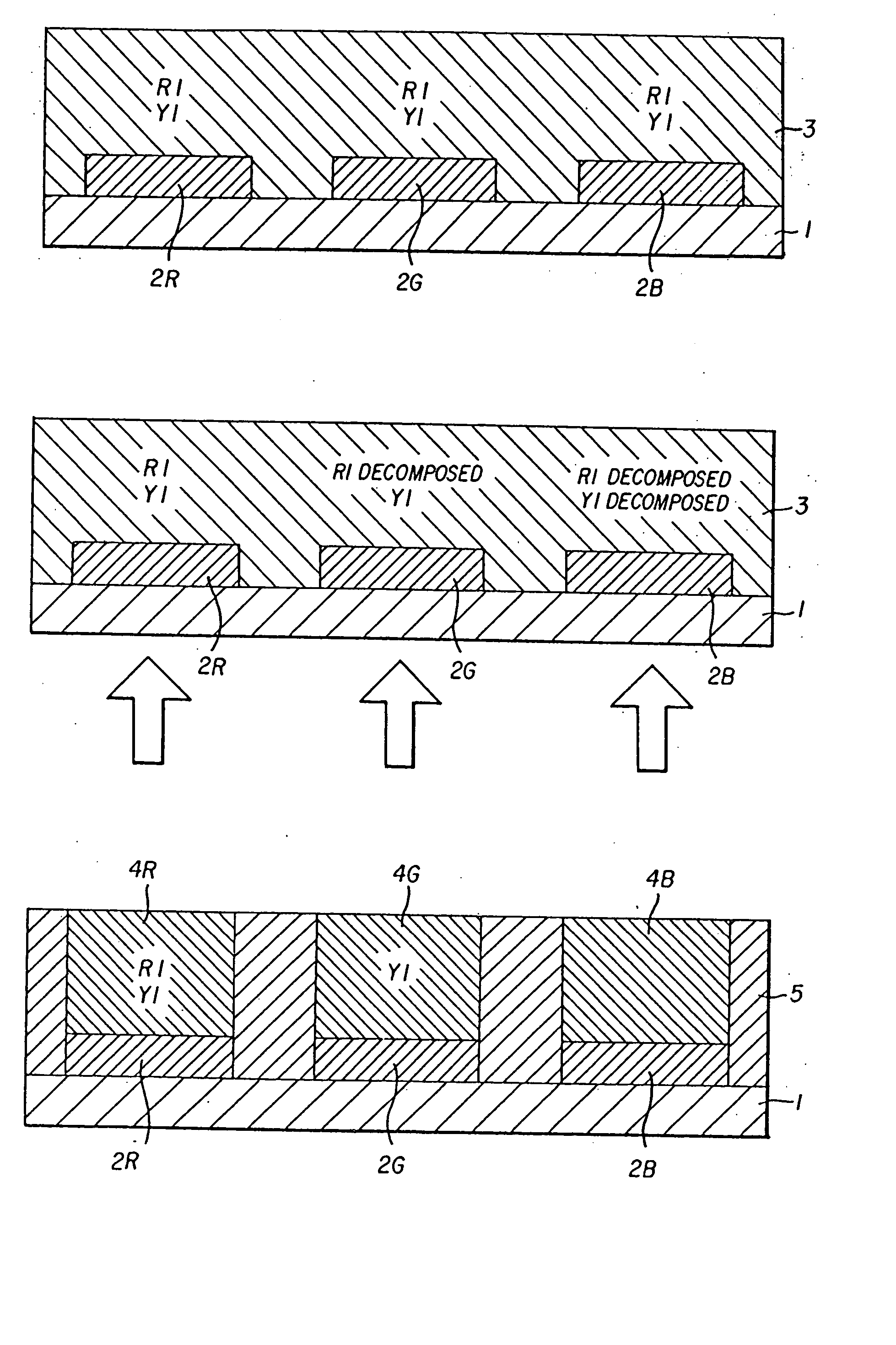
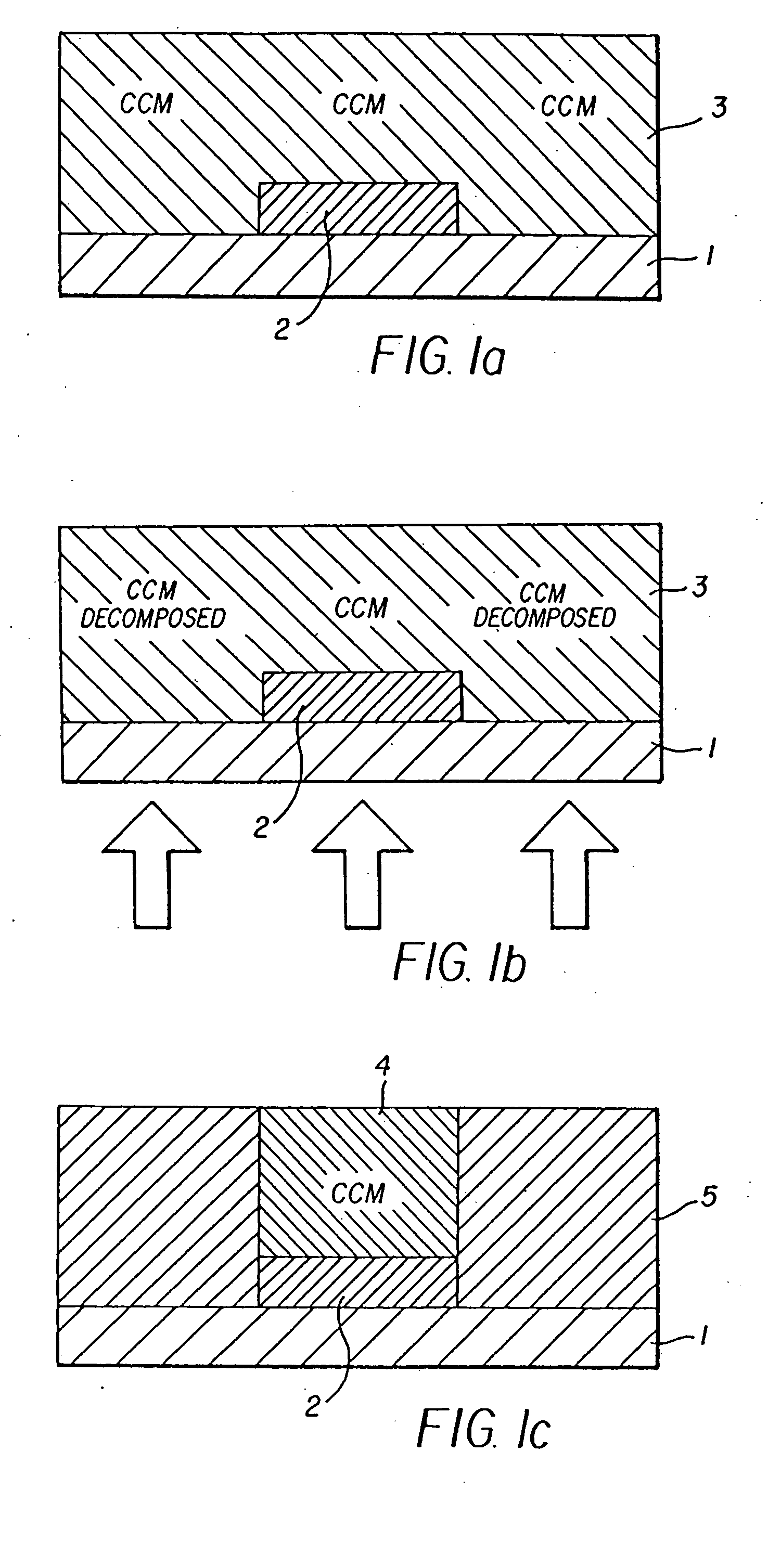
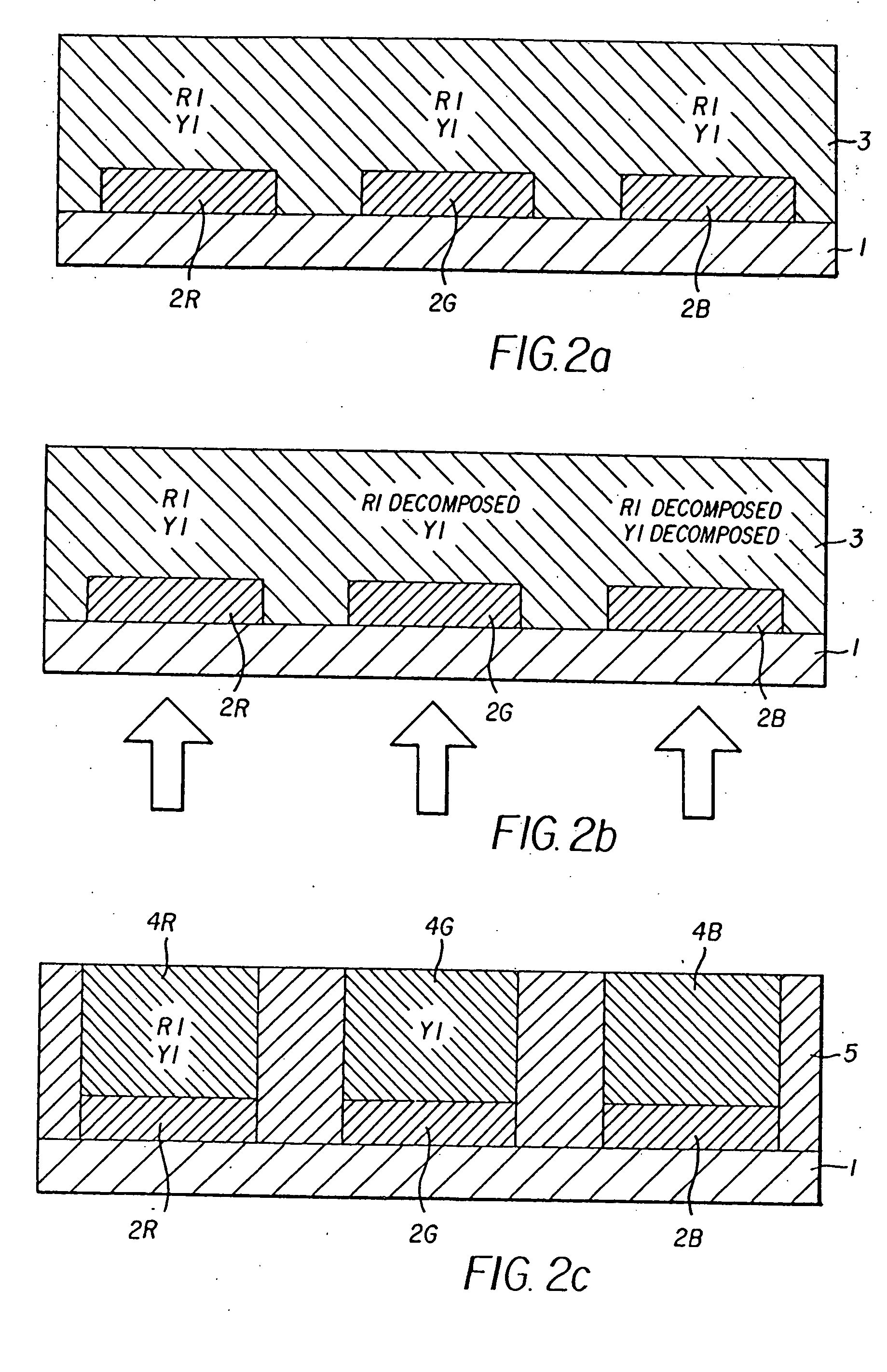
[0079] A blue filter material (Color Mosaic CB-7001 made by Fujifilm Arch Co., Ltd.) was applied using a spin coating method onto transparent glass substrate 1, and patterning was carried out using a photolithography method, thus forming blue color filter layers 2B of thickness 2 μm in a pattern of lines running in a longitudinal direction with a line width of 0.1 mm and a line spacing of 0.33 mm.

[0080] A green filter material (Color Mosaic CG-7001 made by Fujifilm Arch Co., Ltd.) was applied using a spin coating method onto the transparent glass substrate 1 on which blue color filter layers 2B had been formed, and then patterning was carried out using a photolithography method, thus forming green color filter layers 2G of thickness 2 μm in a pattern of lines running in the longitudinal direction with a line width of 0.1 mm and a line spacing of 0.33 mm.

[0081] A red filter material (Color Mosaic CR-7001 made by Fujifilm Arch Co., Ltd.) was applied using a spin coating method, and ...

example 2

[0085] A black mask material (Color Mosaic CK-7000 made by Fujifilm Arch Co., Ltd.) was applied using a spin coating method onto transparent substrate 1, and then patterning was carried out using a photolithography method, thus obtaining black mask 6 of thickness 1.5 μm having therein a plurality of openings each of size 0.33 mm (longitudinal direction)×0.09 mm (transverse direction). The spacing between the openings was 0.03 mm in both the longitudinal and transverse directions.

[0086] Next, a blue filter material (Color Mosaic CB-7001 made by Fujifilm Arch Co., Ltd.) was applied using a spin coating method, and patterning was carried out using a photolithography method, thus forming blue color filter layers 2B of thickness 2 μm in a pattern of lines running in the longitudinal direction with a line width of 0.1 mm and a line spacing of 0.33 mm.

[0087] A green filter material (Color Mosaic CG-7001 made by Fujifilm Arch Co., Ltd.) was applied using a spin coating method onto the tra...

example 3

[0095] The present example is for illustrating the effects of colorant layer 3 used in the third embodiment of the present invention. Amounts of 0.05 g of Coumarin 6 and 0.04 g of Rhodamine B were added to 25 g of a photoresist V259PAP5 (made by Nippon Steel Chemical Co., Ltd.), thus obtaining a coating liquid. The coating liquid was applied to the surface of a transparent substrate (a 1737 glass substrate made by Corning), thus obtaining a colorant layer of thickness 2 μm.

[0096] Next, using a sputtering method, a gas barrier layer comprising an SiO2 film of thickness 0.5 μm was formed such as to cover the colorant layer, thus obtaining a colorant layer substrate. An RF planar magnetron type apparatus was used as the sputtering apparatus, SiO2 was used as the target, and Ar was used as the sputtering gas. The substrate temperature during the SiO2 film formation was set to 80° C.

[0097] An anode (a multi-layered body of Al of thickness 500 nm and ITO of thickness 100 nm), an organic...


PUM

PropertyMeasurementUnit
thicknessaaaaaaaaaa
thicknessaaaaaaaaaa
wavelengthaaaaaaaaaa

Abstract

A color-converting-function-possessing color filter and a method for its manufacture are disclosed. A simplified manufacturing process is provided that makes possible highly detailed patterning. The method of manufacturing the color-converting filter comprises a step of forming color filter layers on a transparent substrate, a step of forming a colorant layer containing a color-converting colorant on the color filter layers, and a step of exposing the colorant layer via the transparent substrate and the color filter layers using colorant-decomposing light, thus forming color-converting layers in positions corresponding to the color filter layers. In usage, a layered body consists of a transparent substrate, color filter layers and a colorant layer as a color-converting-function-possessing filter.

Description

CROSS REFERENCE TO RELATED APPLICATIONS [0001] This application claims priority from Japanese application Serial No. JP 2004-109402, filed on Apr. 1, 2004, and the contents of this document are incorporated herein by reference in their entirety. This application is a continuation-in-part of U.S. application Ser. No. 10 / 795,794, and the contents of this document also are incorporated herein by reference in their entirety.BACKGROUND OF THE INVENTION [0002] A. Field of the Invention [0003] The present invention relates to a method of manufacturing a color-converting filter that enables multi-color display. The color-converting filter can be used for display in image sensors, personal computers, word processors, televisions, facsimiles, audio equipment, video equipment, car navigation equipment, desk-top electronic calculators, telephones, mobile terminal equipment, industrial measuring equipment, and so on. [0004] B. Description of the Related Art [0005] In recent years, as one method ...

Claims


Application Information

Patent Timeline
Patent Type & Authority Applications(United States)
IPC IPC(8): G02B5/20G02F1/13357G02F1/23G09F9/30H01L27/32H01L51/56
CPCG02B5/201H01L51/56H01L27/322G02F1/133617H10K59/38H10K71/00
Inventor KAWAGUCHI, KOJIKOBAYASHIHAMA, TOSHIOSAKURAI, KENYA
Owner SHARP KK
Why Eureka
Try Eureka