
Differential gearing for vehicle

a differential gearing and vehicle technology, applied in the direction of gearing details, gearing, mechanical equipment, etc., can solve problems such as unsatisfactory lubrication, achieve the effects of avoiding the likelihood of a shortage of lubricant oil, preventing an egress of oil through an oil hole, and improving seizure resistan

Inactive Publication Date: 2005-04-28
JTEKT CORP
View PDF4 Cites 10 Cited by
  • Summary
  • Abstract
  • Description
  • Claims
  • Application Information

AI Technical Summary

Benefits of technology

[0006] It is an object of the present invention to provide differential gearing for vehicle which is capable of completely lubricating a planetary gear mechanism and other sliding parts which are received within a housing.
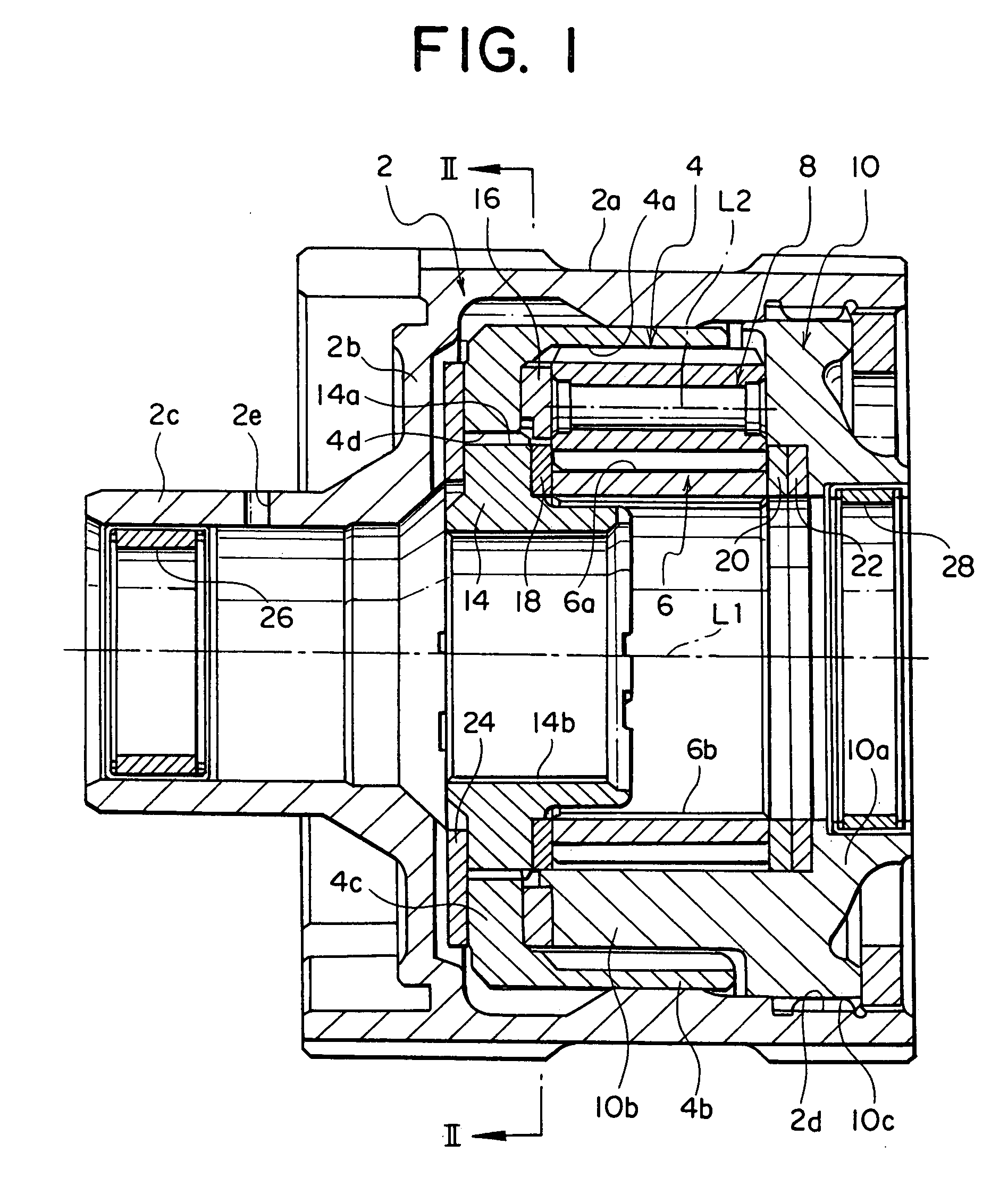
[0009] In the differential gearing for vehicle according to the present invention, a lubricant oil is introduced from a shaft disposed in alignment with the axis to lubricate sliding parts between rotating members which are disposed radialy outward of the shaft. In addition, in a region where the planetary gear mechanism is received, the wall surface of the housing is not formed with an oil hole which extends therethrough, thus preventing an egress of the oil through an oil hole and avoiding the likelihood of a shortage of the lubricant oil. In this manner, a perfect lubrication is enabled, bringing forth advantages that a seizure resistance is improved and the occurrence of noises is reduced.

Problems solved by technology

When the differential gearing case is formed with the through-opening in order to introduce the lubricant oil therein, there is a difficulty that during the running of a vehicle, the lubricant oil stored within the differential gearing case may find its way out through the through-opening, resulting in a dissatisfactory lubrication.

Method used


Image

  • Differential gearing for vehicle
  • Differential gearing for vehicle
  • Differential gearing for vehicle

Examples


Embodiment Construction

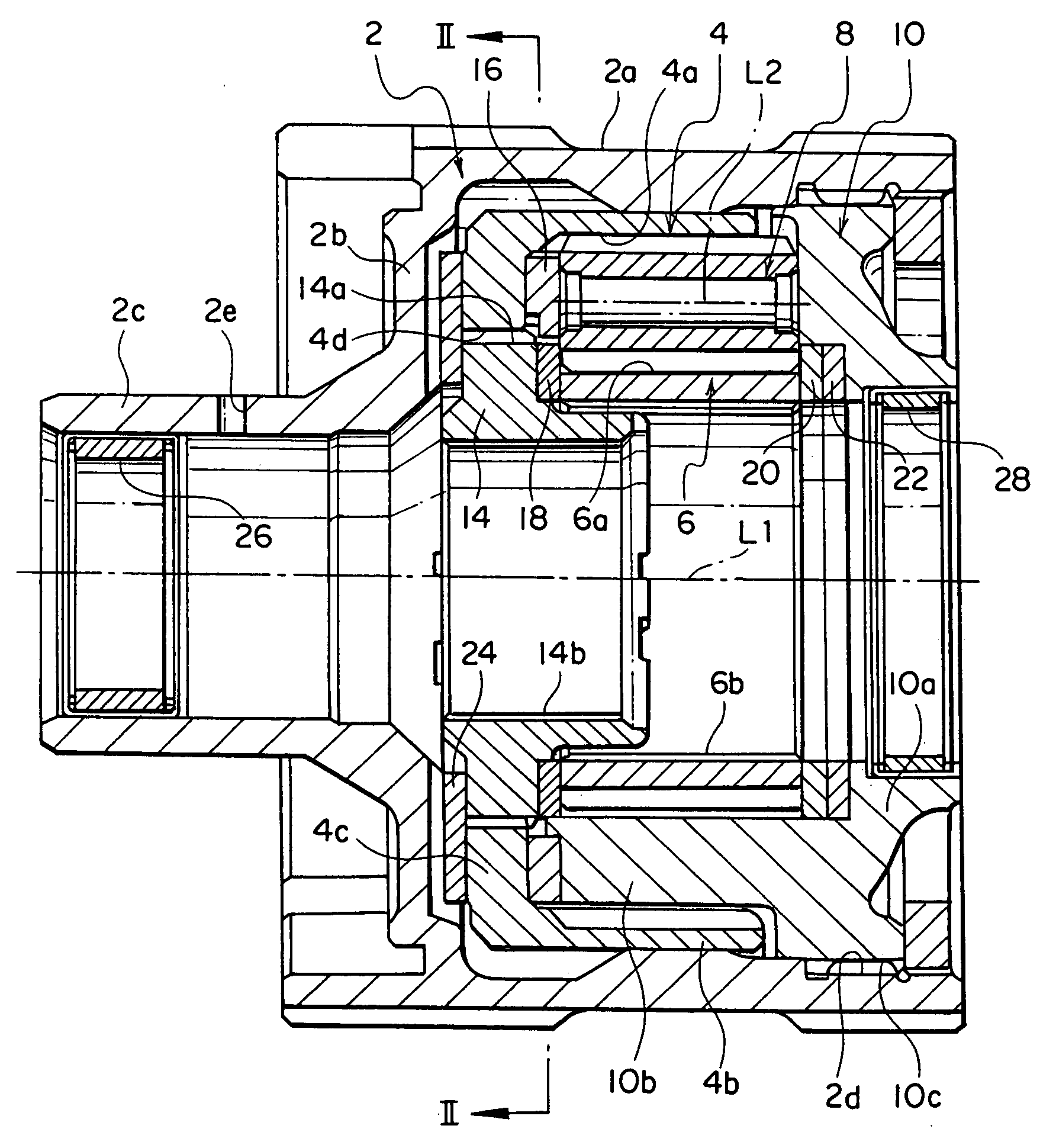
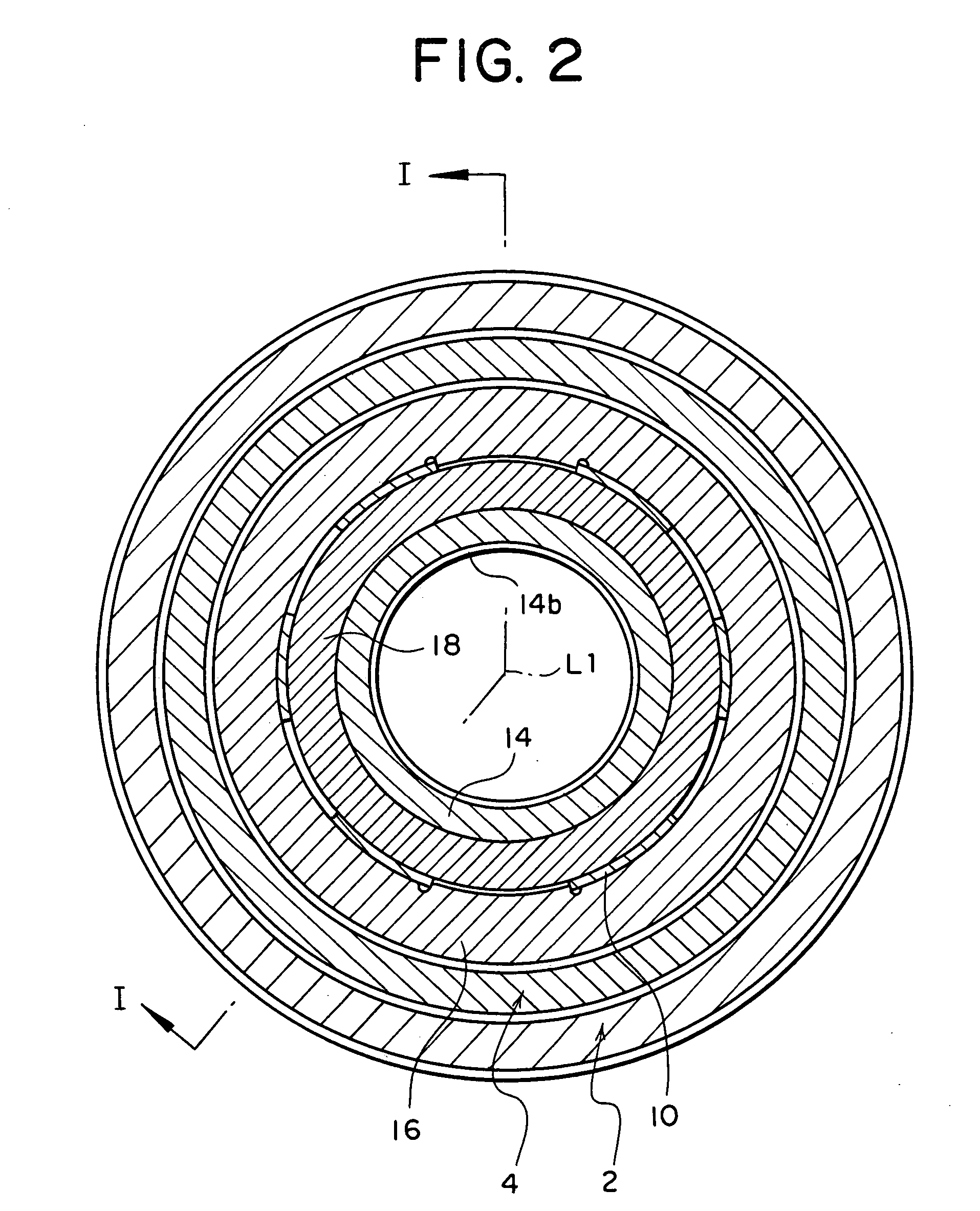
[0012] An embodiment of the present invention will now be described with reference to the drawings. FIG. 1 is a longitudinal section of a differential gearing for vehicle according to one embodiment of the invention (the section being taken along the line I-I shown in FIG. 2), and FIG. 2 is a cross section taken across the line II-II shown in FIG. 1. The differential gearing includes a cylindrical housing 2 in which a planetary gear mechanism comprising an internal gear 4, a sun gear 6, a plurality of planet gears 8 and a planetary carrier 10 which carries the planet gears 8 is received.

[0013] The housing 2 includes a cylindrical portion 2a of an increased diameter which has a bottom 2b at one end or left end as viewed in FIG. 1, and a cylindrical portion of a reduced diameter 2c projects externally from the bottom. An internal gear 4 having internal teeth 4a formed around its inner peripheral surface is rotatably received within the cylindrical portion 2a of an increased diameter ...


PUM


Abstract

An internal gear 4 is fitted within a housing 2, and a sun gear 6 is disposed inside the internal gear in concentric relationship therewith. A plurality of planet gears 8 are carried by a planetary carrier 10 connected to the housing 2 and are in meshing engagement with the internal gear 4 and the sun gear 6. Washers 16, 18, 20, 22 and 24 are disposed in regions where the members 2, 4, 6, 8 and 10 slide against respectively. Hollow shafts are connected to a coupling 14 which is connected to the inner periphery of the internal gear 4 and to the inner periphery of the sun gear 6, and a drive from an engine which is input to the housing 2 is delivered through the both shafts. A lubricant oil is introduced through the shaft to lubricate sliding parts which are disposed radially outward of the shaft. A perfect lubrication of the interior of the differential gearing is achieved, seizure resistance can be improved and the occurrence of noises can be reduced.

Description

CROSS-REFERENCE TO RELATED APPLICATIONS [0001] This application based upon and claims priority under 35 USC § 119 to Japanese patent application No. 2003-350655 filed on Oct. 9, 2003, entire contents of which are incorporated herein by reference. BACKGROUND OF THE INVENTION AND RELATED ART STATEMENT [0002] The present invention relates to a differential gearing for vehicle, and in particular, to a differential gearing for vehicle of a planetary gear type with a torque responsive differential action limiting function. [0003] A differential gearing for vehicle including a planetary gear mechanism comprising an internal gear and a sun gear which are disposed in coaxial relationship, pinion gears which interconnect the internal gear and the sun gear, and a pinion carrier including housing chambers each receiving one of the pinion gears so as to be rotatable therein at the tooth crest is disclosed in Japanese Laid-Open Patent Application No. 4-312,247. [0004] In a conventional differenti...

Claims


Application Information

Patent Timeline
Patent Type & Authority Applications(United States)
IPC IPC(8): F16H48/10F16H48/285F16H48/38F16H57/037F16H57/038F16H57/039F16H57/04
CPCF16H48/10F16H48/28F16H2048/04F16H57/0483F16H57/0479
Inventor KAI, RYUICHIRONISHIJI, MAKOTO
Owner JTEKT CORP
Learn More