Posterior fixation system

Inactive Publication Date: 2005-04-28
BARTIMUS CHRISTOPHER SHAWN
View PDF8 Cites 91 Cited by
  • Summary
  • Abstract
  • Description
  • Claims
  • Application Information

AI Technical Summary

Benefits of technology

[0011] A form of the unique spinal fixation system significantly reduces the limitations and shortcomings

Problems solved by technology

Anterior instrumentation would be installed from the front or onto the front of the spine therefore requiring a low, flat profile on the surface of the spine and having a very difficult means to re-adjust without invasive surgery.
It is not uncommon for individuals who have had fusion at a level to experience problems over time and require fusion on adjacent levels.
One difficult factor in estimating this alignment of the spine is the patients posture, deformities and otherwise individual attributes idealistic or not.
Most cu

Method used


Image

  • Posterior fixation system
  • Posterior fixation system
  • Posterior fixation system

Examples


Embodiment Construction

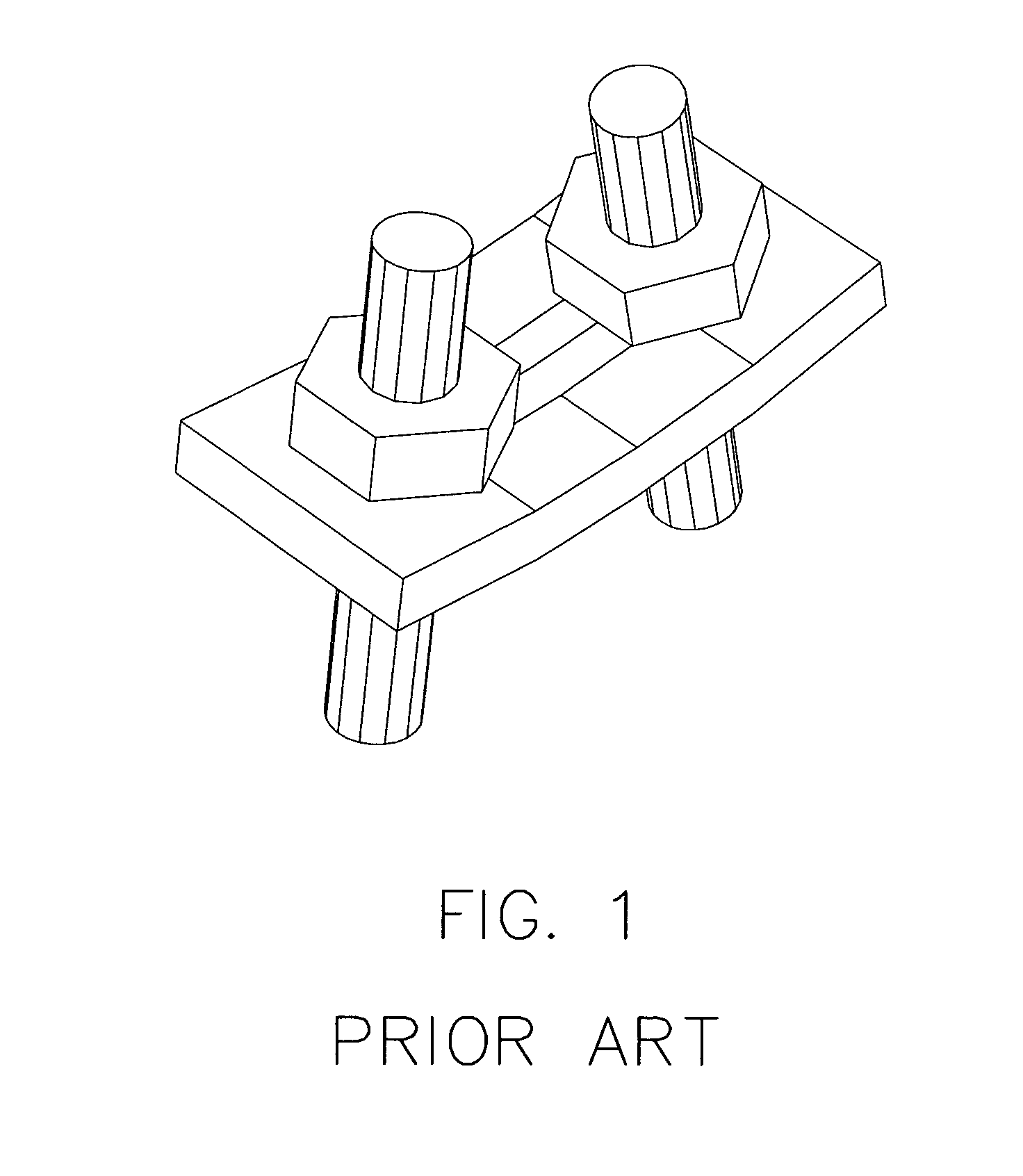
[0030]FIG. 1 refers to a perspective view of prior art showing a typical single level fixation system.

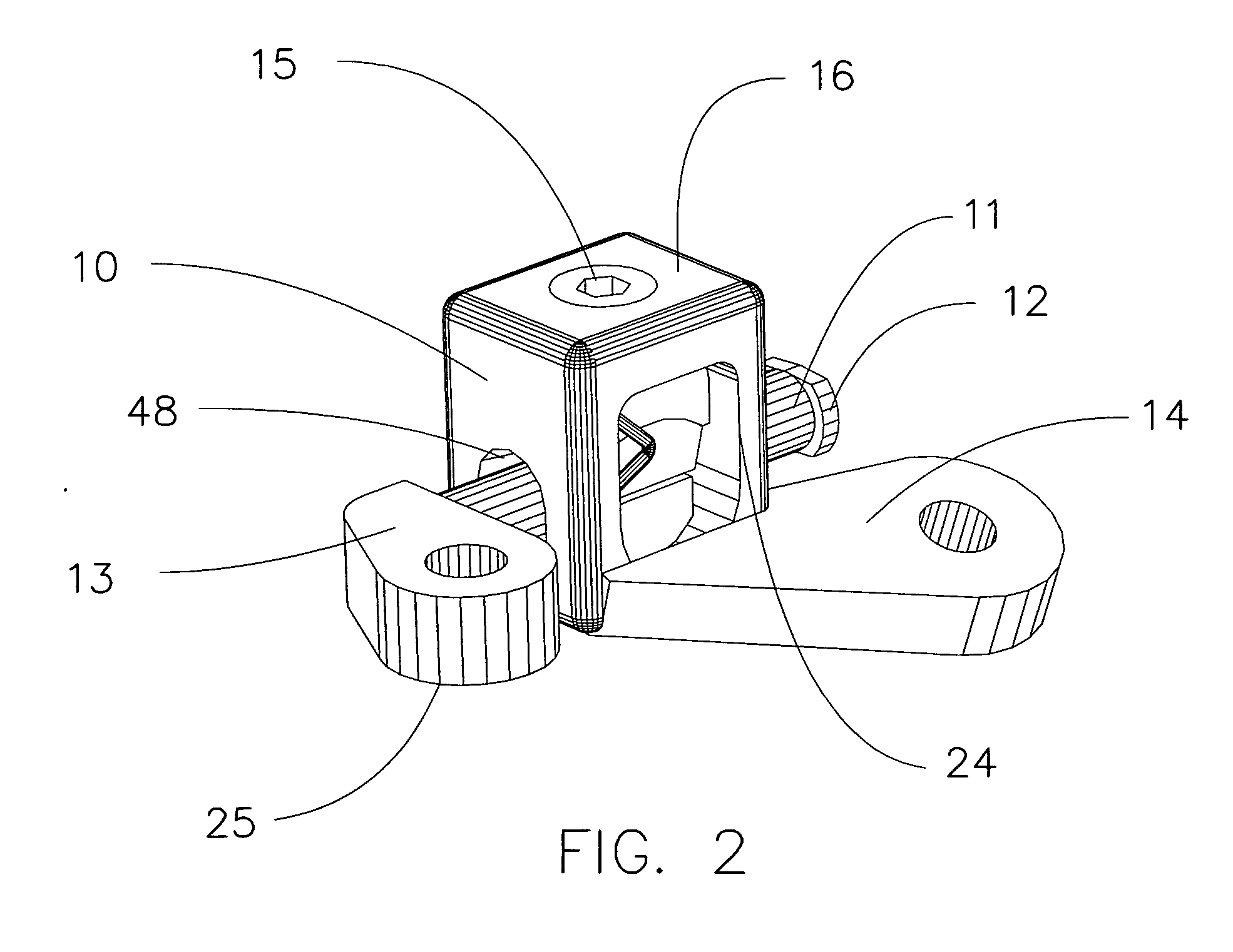
[0031]FIG. 2 refers to a perspective view of an embodiment of a fixation system showing the clamping block 10 and the set screw 15 center mounted in the clamping block. Visible in this view is a cross member 11, a cross member safety stop 12 attached to end of the cross member 11 to prevent the possibility of disassembling during installation. Clearly seen in this view is a clamping block connector 14 attached to the clamping block 10 and a cross member connector 13 attached to the cross member 11. Another feature visible in this view is the flat top with rounded sides 16 reducing any discomfort the recipient might experience.

[0032]FIG. 3 refers to a top view of the preferred embodiment shown in FIG. 2. This embodiment shows the set screw 15 placed center in the clamping block 10. Also shown are cross sectional lines corresponding to the sectional views of FIG. 5 and FIG. 8.

[0033...


PUM


Abstract

A posterior fixation system for the human spine associated with fusion or corrective procedures in achieving proper alignment of the spine with regard to the patient's natural or corrective posture through optional postoperative re-adjustment. The fixation system may include a clamping block secured to a bone segment by pedicle screws or other anchoring device whereby a cross member passes through the multi-axial clamping block and is attached to a bone segment opposite the bridged section. The cross member is clamped and locked into position by engaging the set screw which is also accessible postoperatively by non-invasive means. The fixation of the bone segments promotes healing over an affected area while facilitating a proper alignment of the spine.

Description

BACKGROUND OF INVENTION [0001] Spinal fixation and instrumentation is a well-accepted practice for correcting spinal deformities and other injuries. It is often used in conjunction with inter-vertebral fusion and various fusion devices and methods to facilitate the fixation necessary for the fusion resulting in a successful and anatomically correct fusion. [0002] This spinal instrumentation is often attached to pedicle screws, screws, hooks and clamps which are imbedded or affixed to various spinal bone segments. [0003] Most spinal instrumentation would fall under the category of either anterior or posterior. Anterior instrumentation would be installed from the front or onto the front of the spine therefore requiring a low, flat profile on the surface of the spine and having a very difficult means to re-adjust without invasive surgery. Some in the industry may prefer the anterior approach on certain areas of the spine if it is surgically feasible because the results of an anatomical...

Claims


Application Information

Patent Timeline
IPC IPC(8): A61B17/70
CPCA61B17/7038A61B17/705A61B17/7044
Inventor BARTIMUS, CHRISTOPHER SHAWN
Owner BARTIMUS CHRISTOPHER SHAWN
Why Eureka
Try Eureka