
Apparatus and methods for interfacing acoustic testing apparatus with acoustic probes and systems

a technology applied in the field of acoustic probes and systems, can solve the problems of not generally providing effective diagnosis of the transmission and receiving elements themselves, acoustic imaging devices often lack any direct quantitative method for evaluating either system or probe performance, and acoustic imaging devices are often without direct quantitative methods

Inactive Publication Date: 2005-05-05
GENERAL ELECTRIC CO
View PDF12 Cites 7 Cited by
  • Summary
  • Abstract
  • Description
  • Claims
  • Application Information

AI Technical Summary

Benefits of technology

Enables direct, quantitative evaluation of acoustic probe and system performance, identifying defects and ensuring accurate operation by analyzing signal amplitudes and capacitance, thereby improving diagnostic capabilities beyond qualitative methods.

Problems solved by technology

In some instances, the imaging systems are equipped with internal self-diagnostic capabilities that allow limited verification of system operation, but do not generally provide effective diagnosis of the transmission and receiving elements themselves.
Degradation in performance of these elements is often subtle and occurs as a result of extended transducer use and / or through user abuse.
Acoustic imaging devices therefore often lack any direct quantitative method for evaluating either system or probe performance.
Users and technical support personnel thus sometimes use phantoms that mimic characteristics of the object under study to provide a qualitative method for evaluating image quality and to perform a differential diagnosis between the system and the transducer array, but this technique is widely recognized to be of limited utility.

Method used


Image

  • Apparatus and methods for interfacing acoustic testing apparatus with acoustic probes and systems
  • Apparatus and methods for interfacing acoustic testing apparatus with acoustic probes and systems
  • Apparatus and methods for interfacing acoustic testing apparatus with acoustic probes and systems

Examples


Embodiment Construction

1. Introduction

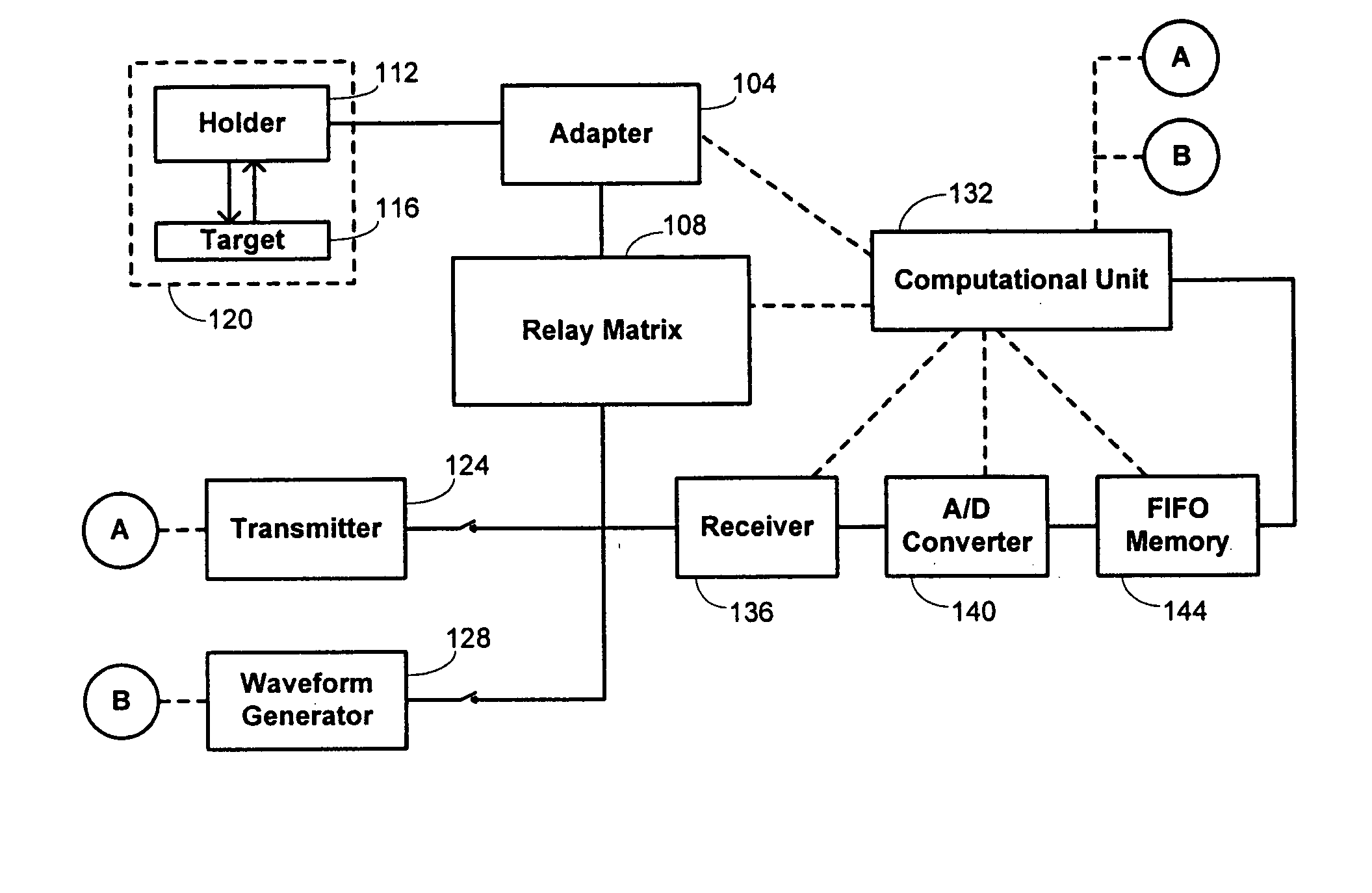
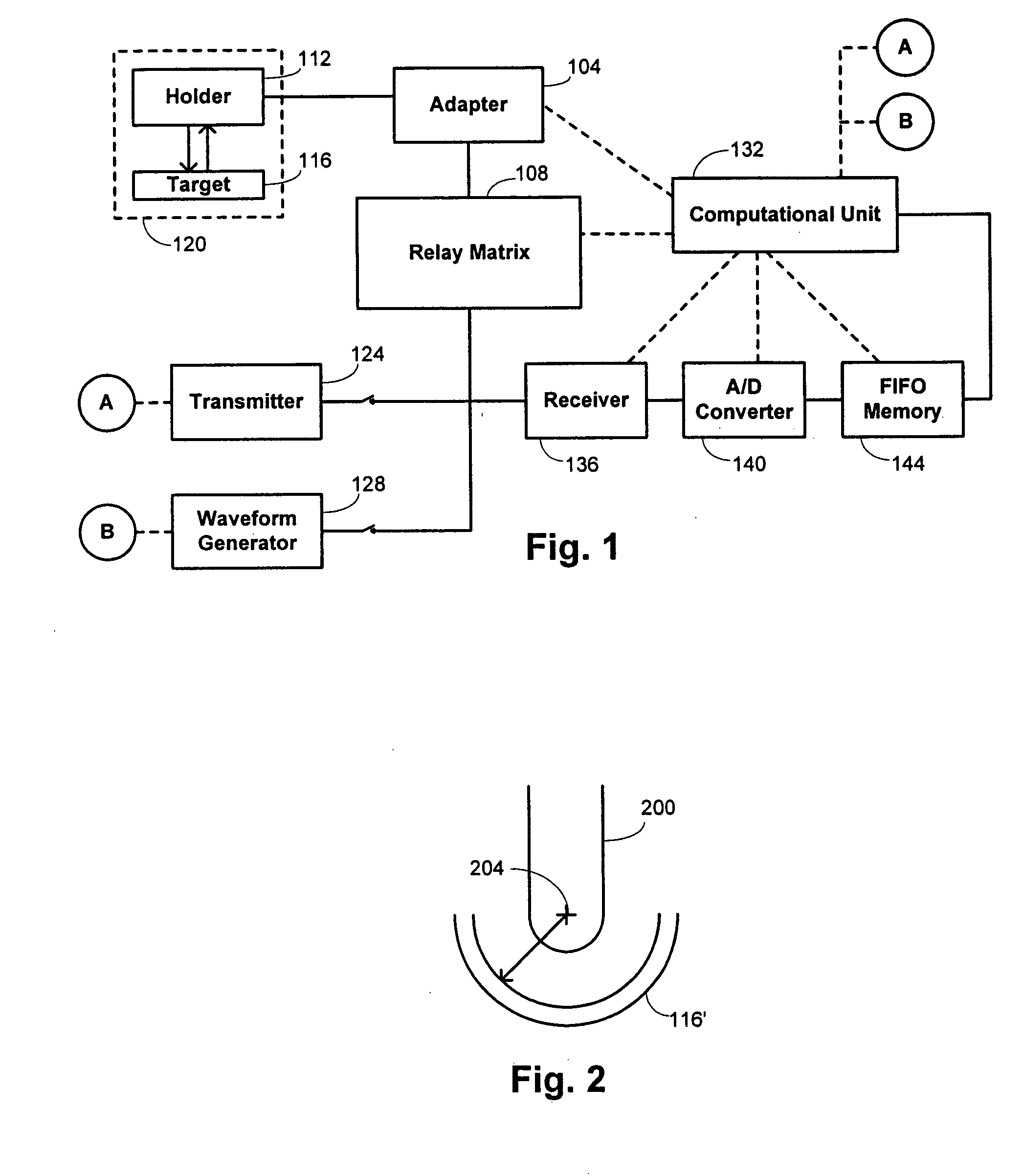
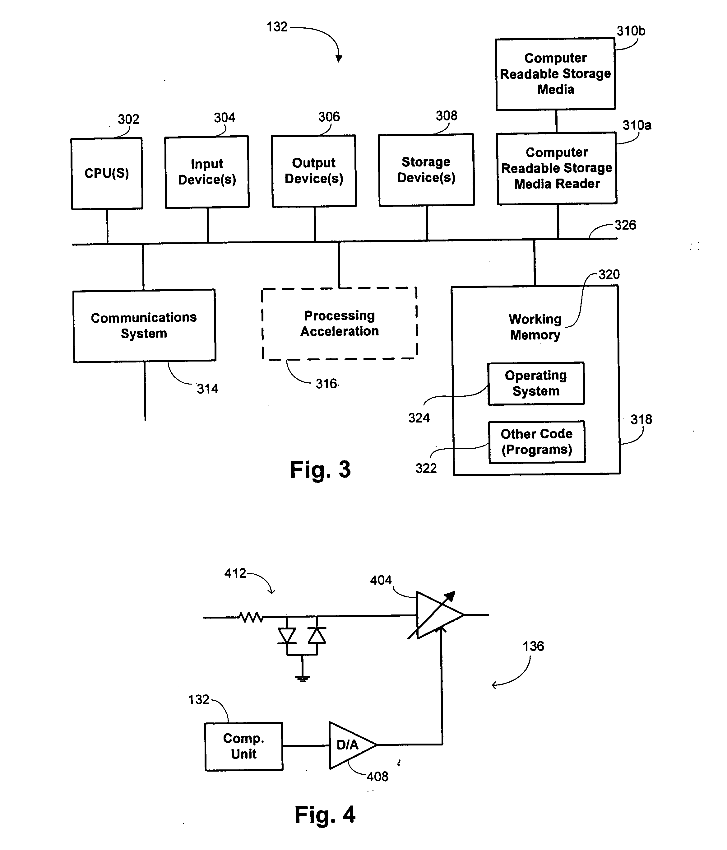
[0030] Embodiments of the invention provide apparatus and methods for testing acoustic probes and systems. Such acoustic probes and systems are sometimes referred to herein collectively as “acoustic devices.” While much of the discussion below specifically discusses apparatus and methods that are suitable for testing ultrasonic probes and systems, this is intended merely for exemplary purposes and the invention is not intended to be limited by the operational frequency characteristics used by the tested probe or system. As illustrated in further detail below, each of the acoustic probes and systems that may be tested with embodiments of the invention includes a plurality of “transducer elements,” which refers to elements adapted to transmit acoustic radiation and / or to receive acoustic radiation. While such elements are referred to generically herein as “transducer elements,” reference is sometimes also made herein to “receiver elements” and to “transmitter elements...


PUM

PropertyMeasurementUnit
resistanceaaaaaaaaaa
frequencyaaaaaaaaaa
frequencyaaaaaaaaaa

Abstract

Methods and apparatus are provided for testing an acoustic device that has multiple transducing elements adapted for conversion between acoustic and electrical signals. An electrical transmission signal is generated. The electrical transmission signal is transmitted to one of a first set of channels through a relay element in accordance with a state of the relay element. The electrical transmission signal is transmitted to one of a second set of channels through a multichannel switch of an adapter in accordance with a state of the multichannel switch. The electrical transmission signal is transmitted to a selected transducing element. An electrical received signal is received from the acoustic device in response to the electrical transmission signal.

Description

CROSS-REFERENCES TO RELATED APPLICATIONS [0001] This application is related to the following concurrently filed, commonly assigned U.S. Patent applications, the entire disclosure of each of which is incorporated herein by reference in its entirety: “APPARATUS AND METHODS FOR TESTING ACOUSTIC PROBES AND SYSTEMS,” by James M. Gessert et al. (Attorney Docket No. 40100-000100US) and “APPARATUS AND METHODS FOR TESTING ACOUSTIC SYSTEMS,” by James M. Gessert et al. (Attorney Docket No. 40100-000200US). BACKGROUND OF THE INVENTION [0002] This application relates generally to acoustic probes and systems. More specifically, this application relates to apparatus and methods for testing acoustic probes and systems. [0003] Acoustic imaging techniques have been found to be extremely valuable in a variety of applications. While medical applications in the form of ultrasound imaging are perhaps the most well known, acoustic techniques are more generally used at a variety of different acoustic frequ...

Claims


Application Information

Patent Timeline
Patent Type & Authority Applications(United States)
IPC IPC(8): G01N29/00G01N29/30G01S15/89
CPCG01N29/30G01S15/89G01N2291/106G01S7/5205
Inventor GESSERT, JAMES M.PHILLIPS, WILLIAM H. JR.MOORE, G. WAYNE
Owner GENERAL ELECTRIC CO
Learn More