Diaphragm monitoring for flow control devices

a technology of flow control device and diaphragm, which is applied in the direction of diaphragm valve, engine diaphragm, instruments, etc., can solve problems such as product loss, and achieve the effect of increasing the sensitivity of the system

Inactive Publication Date: 2005-05-05
SWAGELOK CO
View PDF13 Cites 75 Cited by
  • Summary
  • Abstract
  • Description
  • Claims
  • Application Information

AI Technical Summary

Benefits of technology

[0011] In another embodiment of the invention, multiple strain gages are used. The strain gages are disposed on the diaphragm surface at differing orientations relative to the central axis of the diaphragm. As a resu

Problems solved by technology

However, due to diaphragm flexure and movement, and normal tolerance stackups, the actuator position is

Method used


Image

  • Diaphragm monitoring for flow control devices
  • Diaphragm monitoring for flow control devices
  • Diaphragm monitoring for flow control devices

Examples


Embodiment Construction

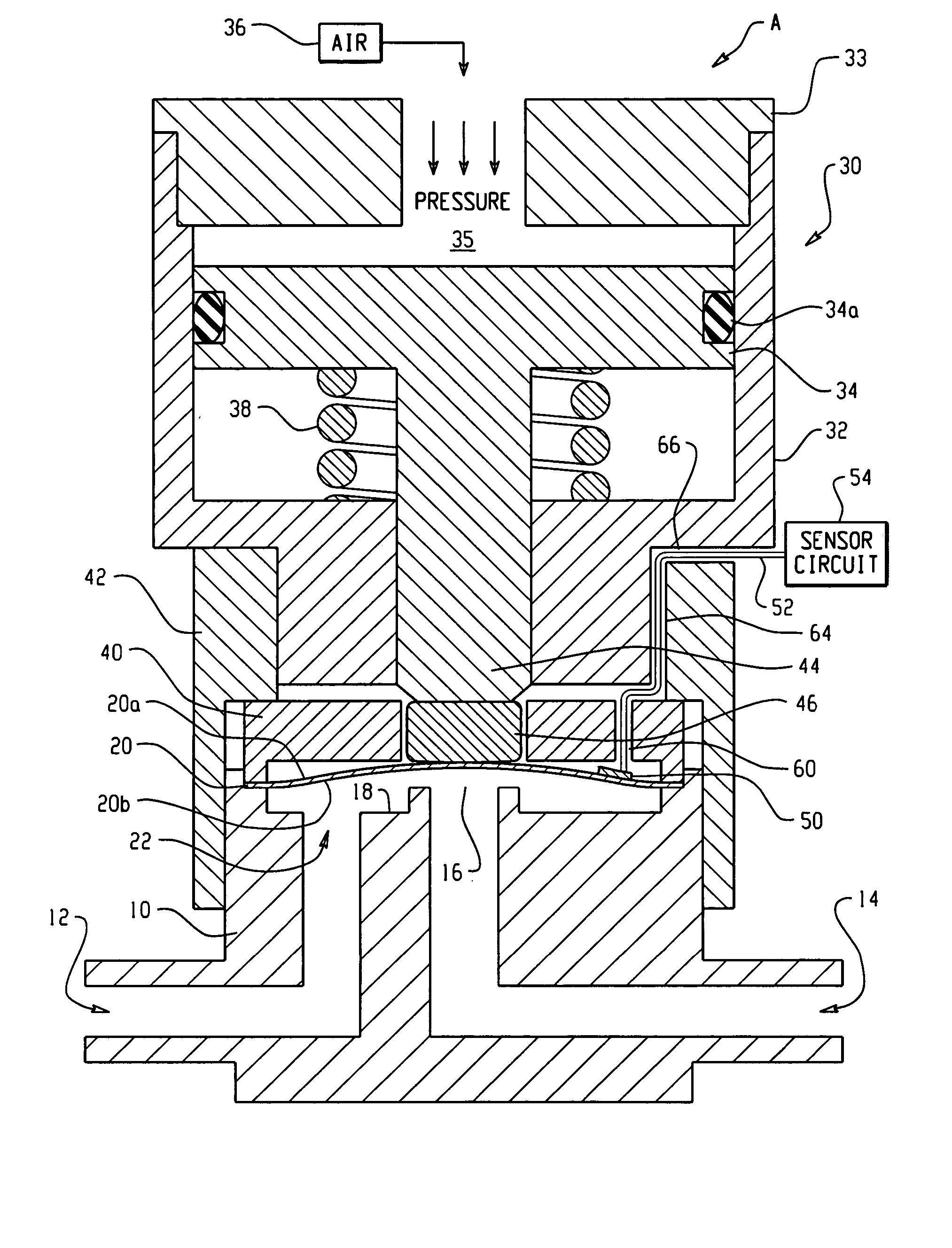
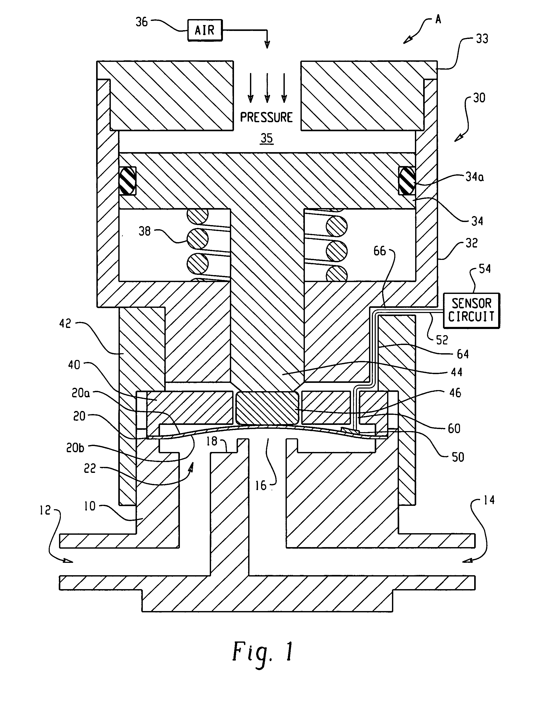
[0024] With reference to FIG. 1, an exemplary diaphragm valve that incorporates one embodiment of the invention is illustrated in longitudinal cross-section. Except for modifications to accommodate the invention, the valve is a commercially available design such as a DP Series diaphragm valve commercially available from Swagelok Company, Solon, Ohio. Suitable diaphragm valve designs are also taught in the following U.S. Pat. Nos. 6,394,417; 6,189,861; 6,123,320; and 4,671,490, the entire disclosures of which are fully incorporated herein by reference. The invention, however, will find application in any diaphragm valve design wherein a sensor can be applied to or operably coupled with a surface or other portion of the diaphragm. The invention may be used with tied diaphragm valve designs as well as non-tied diaphragm designs.

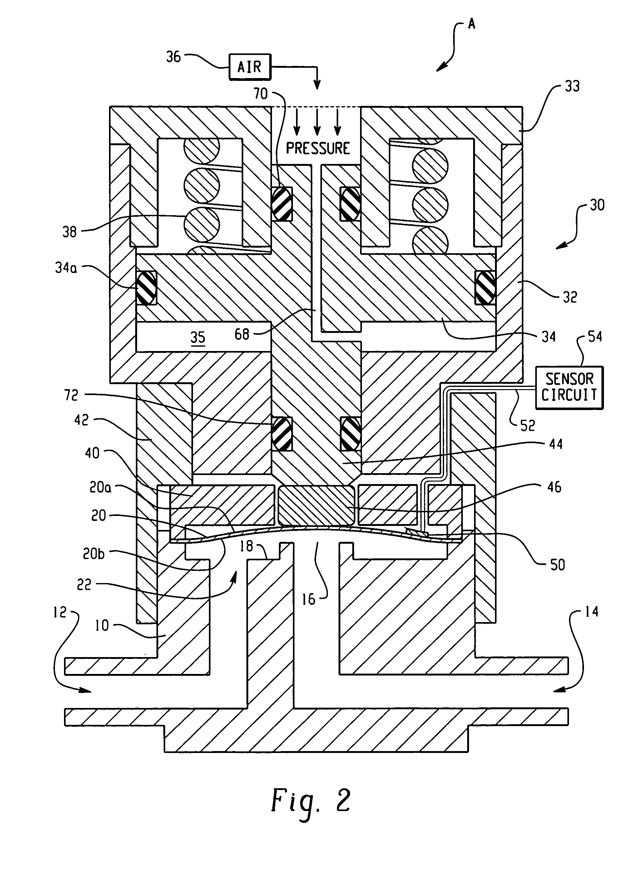
[0025] While various aspects of the invention are described and illustrated herein as embodied in combination in the exemplary embodiments, these various aspec...


PUM


Abstract

Diaphragm position sensing and movement sensing for diaphragm valves is realized with one or more sensors that are directly disposed with the diaphragm or directly sense the diaphragm itself rather than an associated part of a valve. The invention contemplates many different types of sensors and also temperature compensation.

Description

RELATED APPLICATIONS [0001] This application claims the benefit of the following pending U.S. Provisional patent applications, Ser. Nos. 60 / 549,005 filed on Mar. 1, 2004 for DIAPHRAGM VALVE MONITORING, and 60 / 481,463 filed on Oct. 3, 2003 for DIAPHRAGM VALVE MONITORING, the entire disclosures of which are fully incorporated herein by reference.TECHNICAL FIELD [0002] The present invention relates to fluid handling systems and to flow control devices that use diaphragms and are used in such systems. The invention is especially applicable to valves and regulators used in semiconductor processing, analytical instrumentation, biopharmaceuticals, and so on in any application where accurate feedback of the diaphragm state is desirable. BACKGROUND OF THE INVENTION [0003] Fluid handling systems often include diaphragm valves to regulate and control fluid flow within a system. Some fluid handling systems control flow of high purity materials or toxic materials or very expensive biopharmaceuti...

Claims


Application Information

Patent Timeline
IPC IPC(8): F16K7/14F16K7/17F16K31/122F16K37/00
CPCF16K7/14F16K7/17F16K37/0041F16K31/1226F16K31/1221F16K7/12F16K31/122F16K37/00
Inventor ALES, RICHARD A.GLIME, WILLIAM H.
Owner SWAGELOK CO
Why Eureka
Try Eureka