
Heated device and method of redundant temperature sensing

Inactive Publication Date: 2005-05-05
NORDSON CORP
View PDF6 Cites 61 Cited by
  • Summary
  • Abstract
  • Description
  • Claims
  • Application Information

AI Technical Summary

Benefits of technology

[0006] The invention generally provides a device for carrying a heated liquid and controlling the temperature of the heated liquid which includes a redundant temperature sensing system having at least two temperature sensing devices. In the event that the first temperature sensing device fails or malfunctions, the second temperature sensing device can take over the temperature sensing function. The temperature sensing function can be switched manually by the user or automatically by a controller upon sensing the failure or malfunction. Since both temperature sensing devices are incorporated into the heated device, costly downtime and maintenance can be avoided. The heated device can, for example, be a heated hose or other adhesive carrying component of a hot melt adhesive system.

Problems solved by technology

Occasionally, temperature sensing devices such as RTDs, will fail or otherwise malfunction.
This leads to erroneous temperature readings or to a complete inability to detect the temperature of the intended target, such as the liquid adhesive being carried within a heated device such as a hose.
The downtime and replacement costs can be relatively high, especially as compared to the cost of the RTD itself.
It may also be some time before a defective RTD is discovered and this can result in improper heating of the adhesive for the same amount of time.
If overheating of adhesive occurs, char and other negative effects of the overheating can harm the hot melt system and / or the products receiving the hot melt adhesive.
Underheating the adhesive can, for example, adversely affect adhesive properties such as bond strength.

Method used


Image

  • Heated device and method of redundant temperature sensing
  • Heated device and method of redundant temperature sensing
  • Heated device and method of redundant temperature sensing

Examples


Embodiment Construction

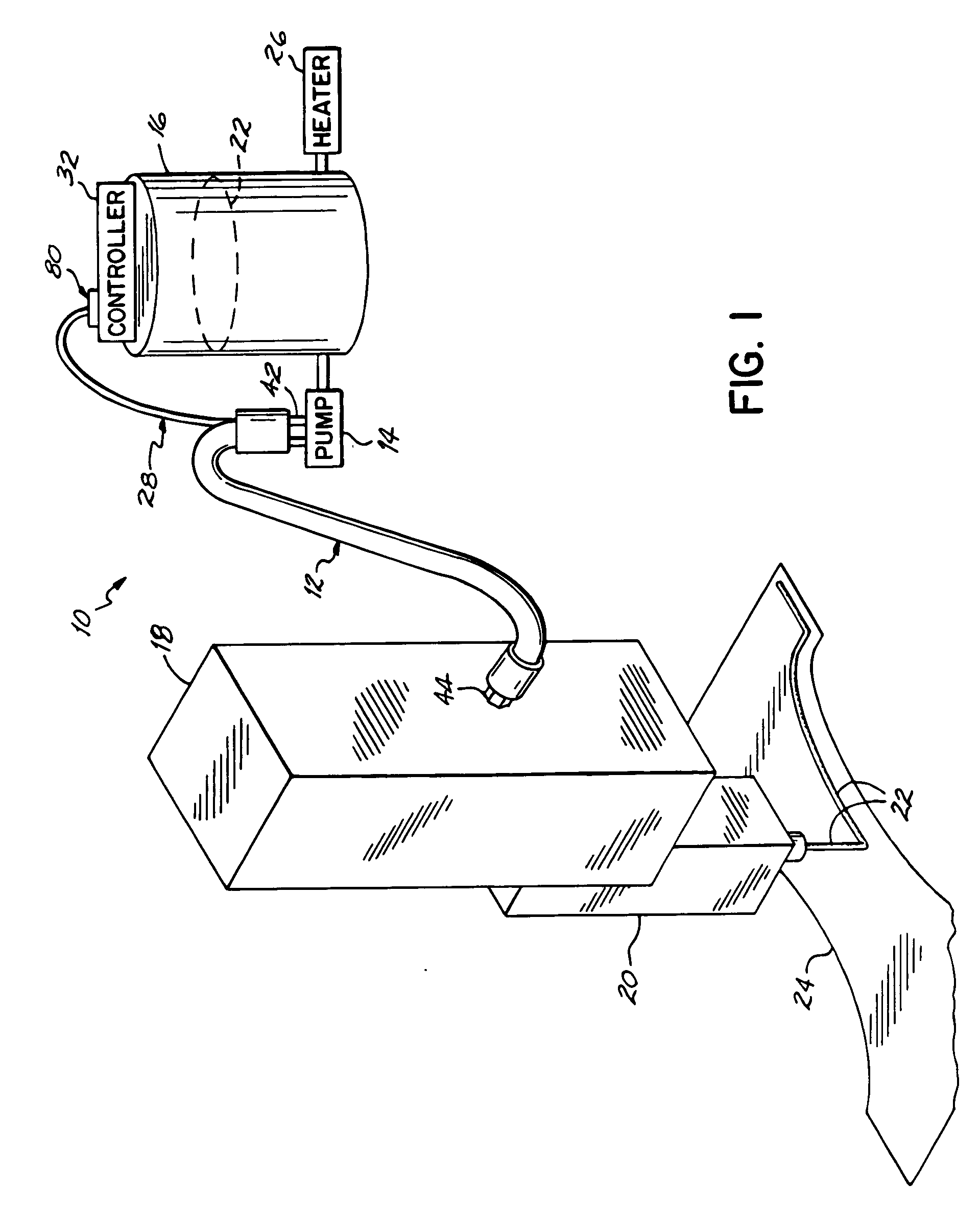
[0017] With reference to FIG. 1, an adhesive dispensing apparatus 10 includes a hose 12 constructed in accordance with the principals of the present invention. The hose 12 connects a pump 14, which is coupled to supply tank 16, to a manifold 18, which is coupled to an adhesive dispensing gun 20. As such, pump 14 can transport an adhesive 22, such as hot melt, for example, from supply tank 16 via hose 12 to adhesive dispensing gun 20. The adhesive dispensing gun 20 selectively dispenses adhesive 16 onto a substrate 24 such as a nonwoven web used in the construction of a diaper. A heater 26 is associated with supply tank 16 and is selectively controlled to maintain the adhesive 22 within supply tank 16 within a predetermined elevated temperature range. The hose 12 includes an wire harness 28 which is connected to a controller 32 associated with the supply tank 16.

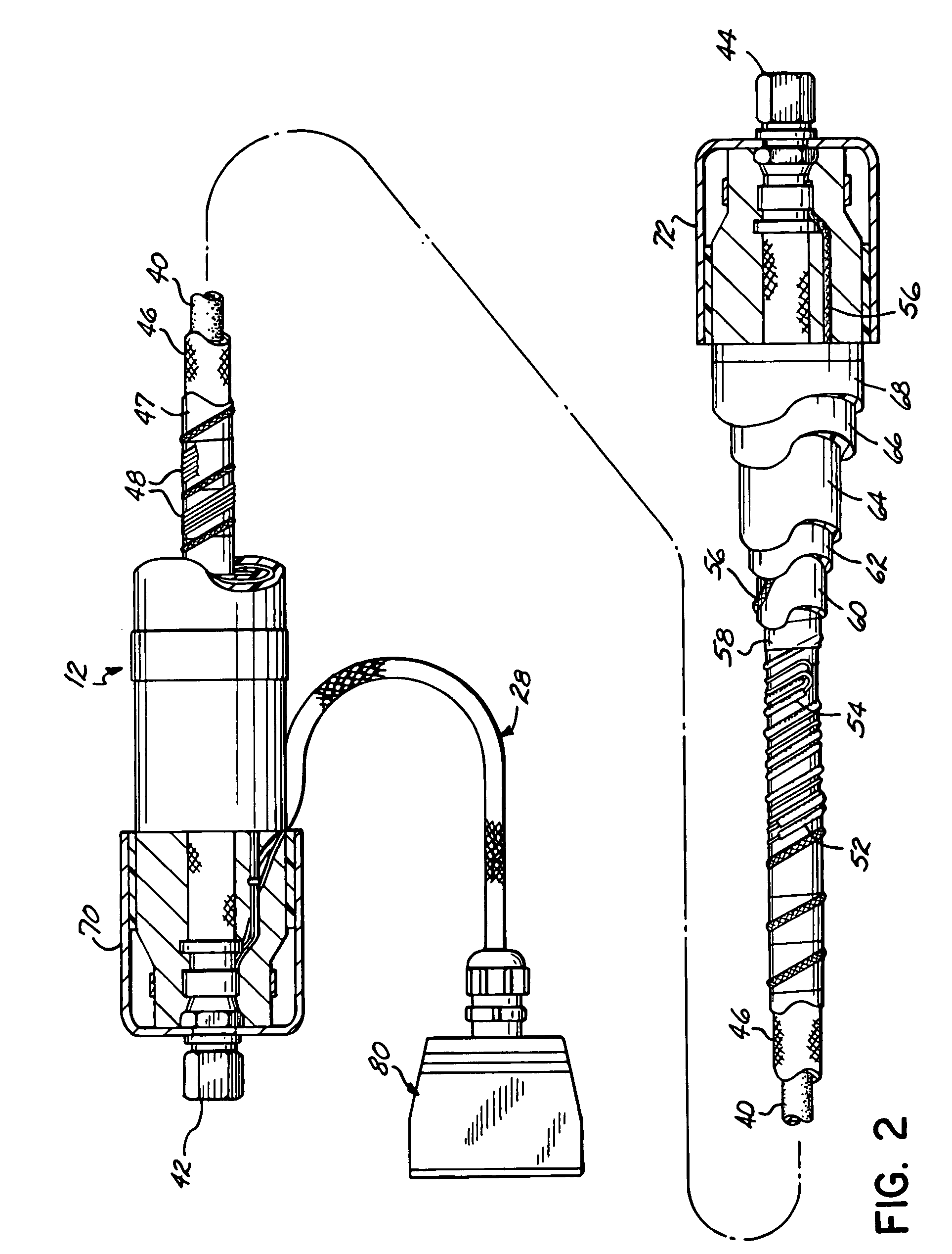
[0018] With reference to FIG. 2, the hose 12 includes a tube 40 with an inlet end 42 which connects to pump 14 and a disch...


PUM


Abstract

A device for carrying a heated liquid, and controlling the temperature of the heated liquid includes a liquid conveying element including a passage for carrying the heated liquid. First and second temperature sensing devices are operatively associated with the liquid conveying element to sense the temperature of the heated liquid. A controller is actively connected to the first temperature sensing device. The first temperature sensing device thereby senses the temperature of the heated liquid in the passage and conveys the temperature information or readings to the controller for use in the heater control. The second temperature sensing device is capable of being actively connected to the controller upon failure or malfunction of the first temperature sensing device.

Description

FIELD OF THE INVENTION [0001] The present invention generally relates to devices, such as hoses used to carry heated liquids and incorporating temperature sensors, such as resistive temperature detectors (RTDs). BACKGROUND OF THE INVENTION [0002] Various manufacturing processes involve the transmission of a heated liquid from a supply tank, through a hose, and to a liquid dispensing device which deposits the heated liquid into a container or onto a substrate. Some of the heated liquids are hot melt adhesives which solidify at room temperature. Accordingly, a hot melt adhesive must be heated and liquified so it can flow from the supply tank, through the hose, and out the liquid dispensing device. To liquify and subsequently maintain the hot melt adhesive within an appropriate temperature range, the supply tank, the hose, and the dispensing gun are selectively heated by individual heating devices operatively associated with each respective component. To monitor the temperature of the ...

Claims


Application Information

Patent Timeline
IPC IPC(8): A61F13/15B05B7/16B05C11/10H05B1/02
CPCB05C11/1042B05B7/1693
Inventor RATERMAN, JOHN M.TAYLOR, EDWARD C.
Owner NORDSON CORP
Learn More