
System and method for dispensing a fluid to a liquid spraying device

a technology of liquid spraying device and fluid, which is applied in the direction of liquid/fluent solid measurement, container, volume measurement, etc., can solve the problems of solvents that are often hazardous to human health, affecting the quality of liquid spraying, etc., and achieves the effect of convenient use and inexpensive manufacturing

Inactive Publication Date: 2005-05-05
YECHOURON SIMON
View PDF13 Cites 36 Cited by
  • Summary
  • Abstract
  • Description
  • Claims
  • Application Information

AI Technical Summary

Benefits of technology

[0018] Advantageously, the bag is relatively inexpensive to manufacture and reduces an amount of cleaning solvent required to clean the liquid spraying device after its use. In addition, the bag allows to reduce costs as it eliminated the need for a disposable paint mixing cup. Also, the bag allows storing unused paint relatively easily and relatively inexpensively.
[0022] Advantageously, the system is relatively easy to use and allows preparing a bag of fluid to spray, such as for example paint, prior to attaching the bag to the liquid spraying device. Also, the system is relatively inexpensive to manufacture. Furthermore, in some embodiments, the system had all the advantages of the above-described bag as such a bag is part of the system.

Problems solved by technology

Such solvents are typically relatively expensive and also damaging to the environment.
Also, these solvents are sometimes hazardous to human health.
Since the mixing cup is disposable, there is an additional cost to be incurred by the painter each time a new paint is mixed.
Furthermore, cleaning the gun and the paint gun cup, along with the lid, is time consuming.
Such lids represent a substantial portion of the costs incurred in manufacturing these reservoirs.
The systems described in these Patents have a disadvantage of requiring the use of a paint mixing cup, which either needs to be cleaned or disposed of after use.
Furthermore, in the system described in U.S. Pat. No. 5,582,350, it is relatively inconvenient to store unused paint that might be left after painting.
Also, it is likely that a small amount of paint drips into the cup when the liner is removed, which requires that the cup be cleaned.

Method used


Image

  • System and method for dispensing a fluid to a liquid spraying device
  • System and method for dispensing a fluid to a liquid spraying device
  • System and method for dispensing a fluid to a liquid spraying device

Examples


Embodiment Construction

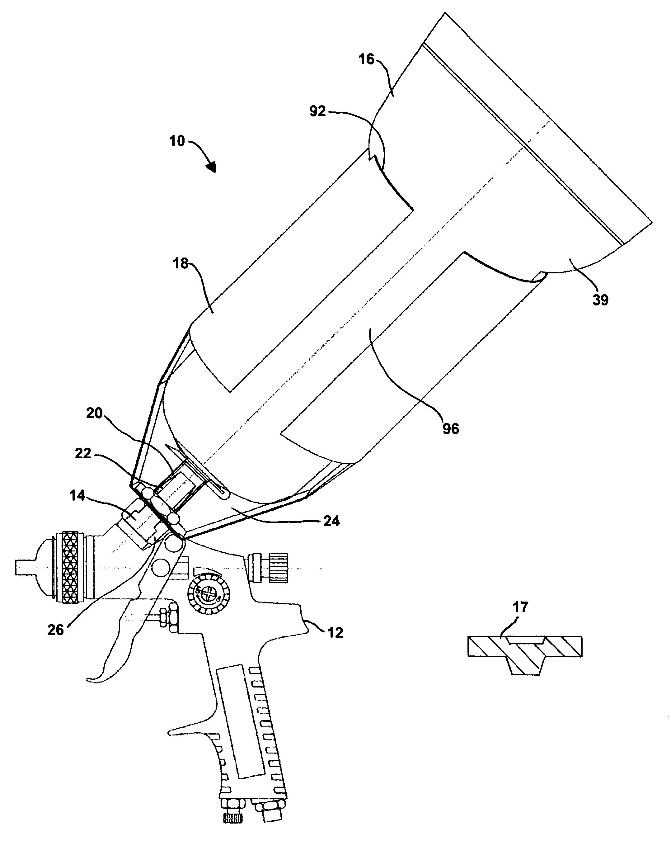
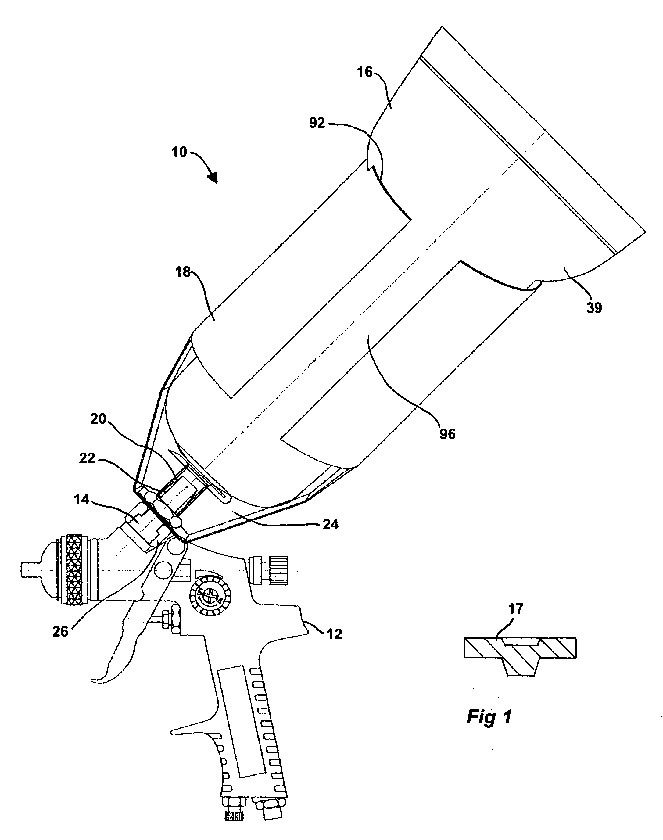
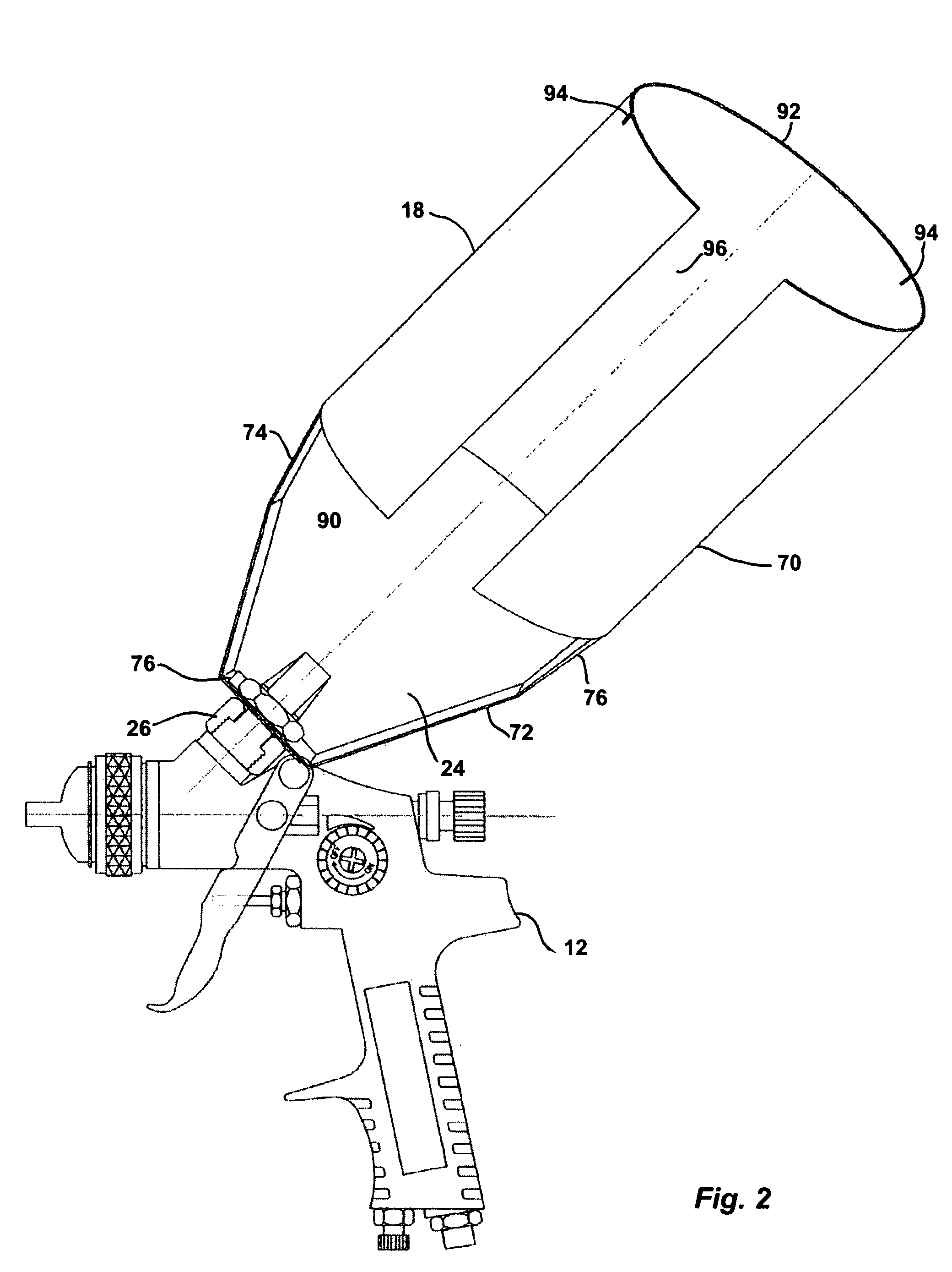
[0040]FIGS. 1 and 2 illustrate a system 10 for dispensing a fluid to a liquid spraying device 12. An example of a liquid spraying device is a spray paint gun. However, the reader skilled in the art will readily appreciate that any suitable liquid spraying device is usable in conjunction with the invention. The liquid spraying device 12 defines a fluid receiving aperture 14. The fluid receiving aperture 14 receives the fluid from the system 10.

[0041] The system 10 includes a substantially flexible bag 16 for containing the fluid to dispense. The bag 16 includes a dispensing portion 20 having an outlet 22 for dispensing the fluid.

[0042] The system 10 further includes a frame 18 for receiving the bag 16. The frame 18 is connectable to the liquid spraying device 12. The frame 18 includes a frame aperture 24 for allowing an intended user to connect the bag 16 to the liquid spraying device 12 further to the bag having 16 been filled with the fluid to dispense.

[0043] As better seen in F...


PUM


Abstract

A bag for containing a fluid and dispensing the fluid into an article, the article defining a fluid receiving aperture. The bag includes a substantially deformable body, the body defining a cavity for containing the fluid; a substantially rigid dispensing portion, the dispensing portion including an inlet, an outlet and a passageway extending therebetween, the inlet being in fluid communication with the cavity; and a closing portion extending across the dispensing portion for blocking the latter, the closing portion being puncturable by the article to allow the fluid to flow from the cavity to the fluid receiving aperture through the inlet, the passageway and the outlet.

Description

FIELD OF THE INVENTION [0001] The present invention relates to the dispensing of fluids. More specifically, the present invention is concerned with a system and method for dispensing a fluid to a liquid spraying device. BACKGROUND OF THE INVENTION [0002] A common tool used in the painting industry is a spray gun. A spray gun typically uses compressed air to eject paint contained in a reservoir towards a surface to paint. Many spray guns include a reservoir that feeds the paint into the gun through gravity. Accordingly, the reservoir is located on an upper portion of the spray gun. [0003] A painter typically needs to mix paint components, including for example pigments of different colors and paint additives, to obtain a paint having suitable characteristics. To that effect, in an existing system, the painter uses a disposable paint mixing cup to combine different paint components in appropriate proportions. The paint mixing cup includes marks typically printed on an outside wall of ...

Claims


Application Information

Patent Timeline
IPC IPC(8): B05B7/24B05B9/01B05B9/03B65D35/56
CPCB05B7/2408B05B7/2481B05B7/2478
Inventor YECHOURON, SIMON
Owner YECHOURON SIMON
Learn More