Fast-hopping frequency synthesizer

a frequency synthesizer and fast-hopping technology, applied in the direction of oscillator generators, pulse automatic control, electrical equipment, etc., can solve the problems of taking a long time for the frequency synthesizer to switch and typically not meeting the demands of the system

Inactive Publication Date: 2005-05-05
STACCATO COMM
View PDF6 Cites 90 Cited by
  • Summary
  • Abstract
  • Description
  • Claims
  • Application Information

AI Technical Summary

Problems solved by technology

Since the PLL typically is unable to instantaneously lock onto a frequency, it usually takes some time for the frequency synthesizer to switch from one output frequency to another.
While existing frequency synthesizers are adequate for communication syste

Method used


Image

  • Fast-hopping frequency synthesizer
  • Fast-hopping frequency synthesizer
  • Fast-hopping frequency synthesizer

Examples


Embodiment Construction

[0014] The invention can be implemented in numerous ways, including as a process, an apparatus, a system, a composition of matter, a computer readable medium such as a computer readable storage medium or a computer network wherein program instructions are sent over optical or electronic communication links. In this specification, these implementations, or any other form that the invention may take, may be referred to as techniques. In general, the order of the steps of disclosed processes may be altered within the scope of the invention.

[0015] A detailed description of one or more embodiments of the invention is provided below along with accompanying figures that illustrate the principles of the invention. The invention is described in connection with such embodiments, but the invention is not limited to any embodiment. The scope of the invention is limited only by the claims and the invention encompasses numerous alternatives, modifications and equivalents. Numerous specific detai...


PUM


Abstract

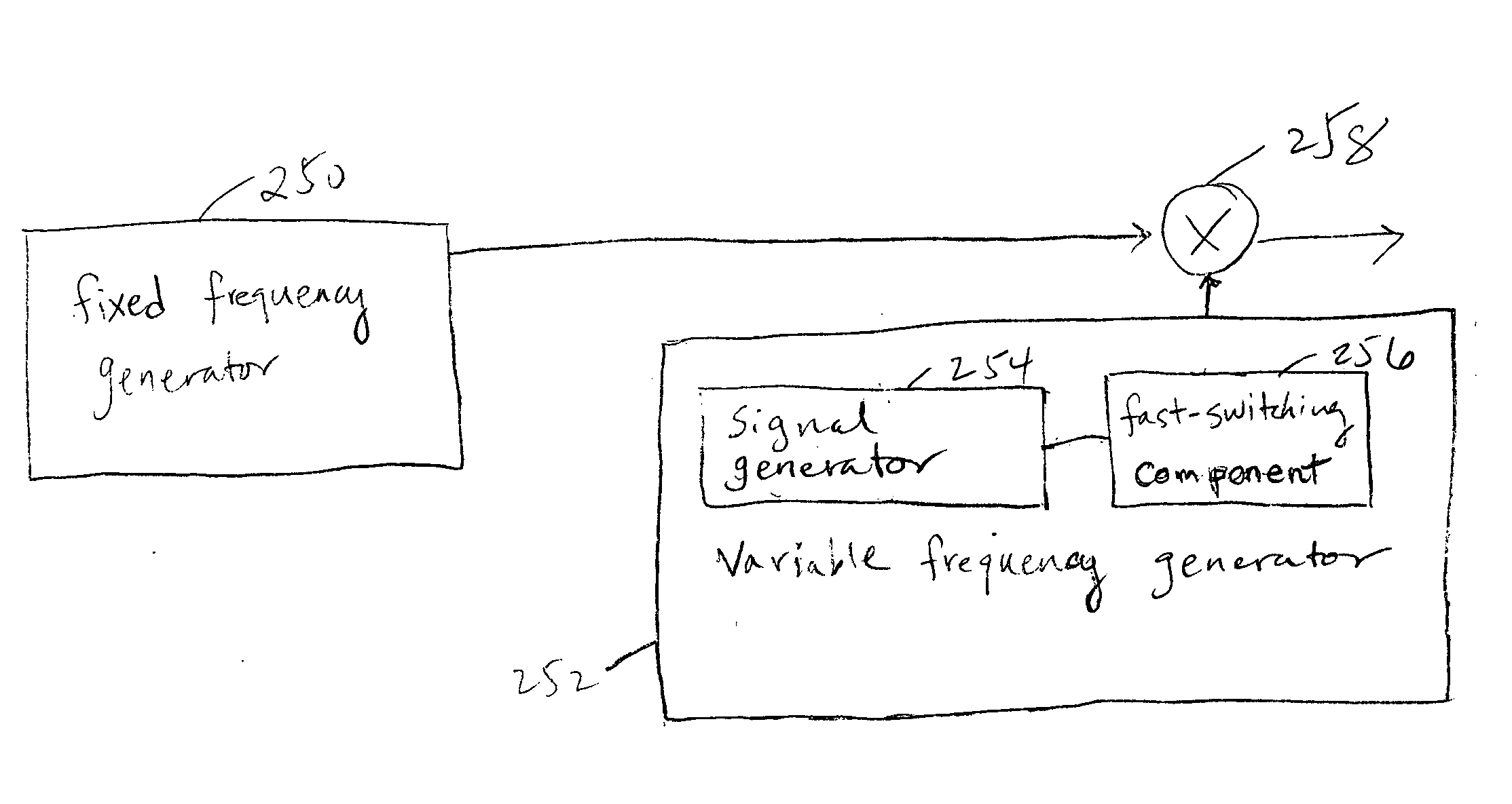
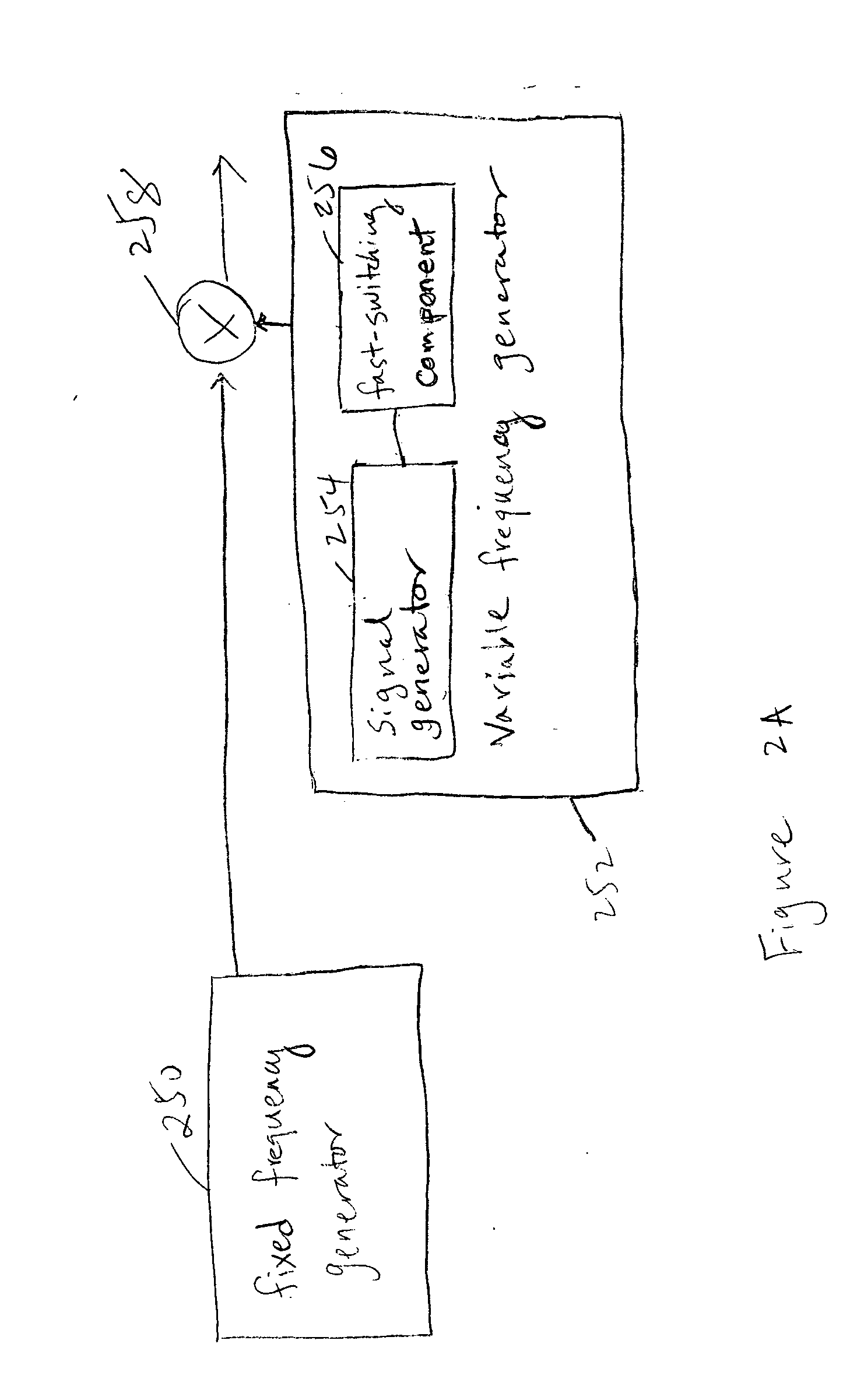
A frequency synthesizer is disclosed. The frequency synthesizer comprises a fixed frequency generator configured to generate a fixed frequency signal, a variable frequency generator configured to generate a variable frequency signal, wherein the fixed frequency signal and the variable frequency signal are combined to provide a fast-hopping output signal.

Description

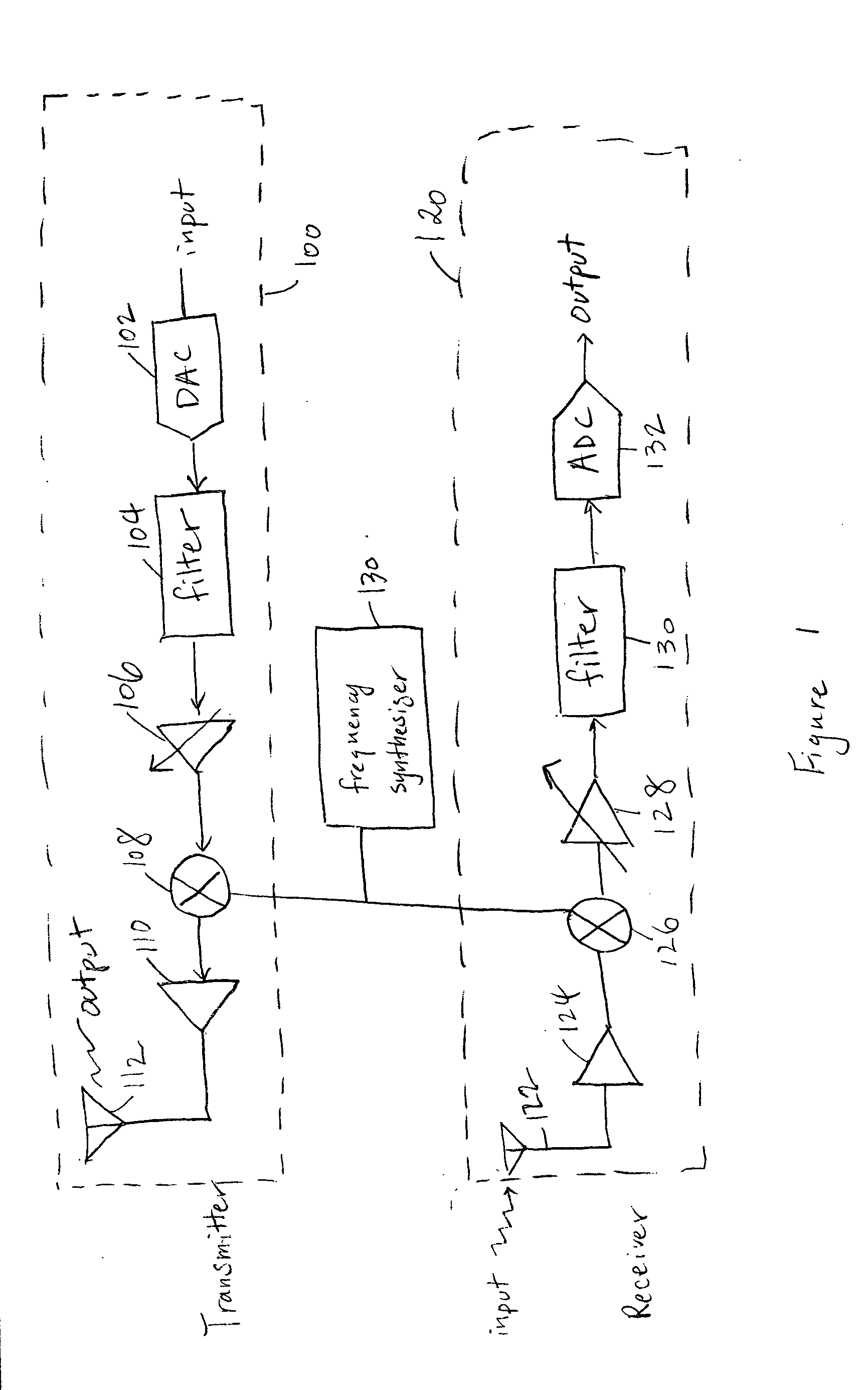
FIELD OF THE INVENTION [0001] The present invention relates generally to frequency synthesizers. More specifically, a fast-hopping frequency synthesizer is disclosed. BACKGROUND OF THE INVENTION [0002] Frequency synthesizers are widely used in communication systems. Existing frequency synthesizers typically include a reference frequency and a phase locked loop (PLL). The PLL takes the reference frequency as its input, and is configurable to provide a range of output frequencies based on the reference input via a feedback loop. [0003] A PLL typically includes a voltage controlled oscillator (VCO) that is configured in a feedback loop to provide an output signal at the desired frequency. In some systems, the desired output frequency changes over time. The switching from one output frequency to another is referred to as frequency hopping or channel hopping. Since the PLL typically is unable to instantaneously lock onto a frequency, it usually takes some time for the frequency synthesiz...

Claims


Application Information

Patent Timeline
IPC IPC(8): H03B1/00H03DH03L7/00
CPCH03L7/083H03L7/0995H03L7/183H03L7/24H03L7/189H03L7/23H03L7/187
Inventor MEACHAM, DAN
Owner STACCATO COMM
Why Eureka
Try Eureka