Circuits and methods for implementing sub-integer-N frequency dividers using phase rotators

a phase rotator and sub-integer technology, applied in the direction of pulse automatic control, oscillator generator, pulse technique, etc., can solve the problem of channel resolution not significantly tight to warrant a full-blown synthesizer, the output signal cannot be manipulated arbitrarily large, and the glitches of the output signal cannot be eliminated, so as to reduce the glitches

Active Publication Date: 2009-02-03
INT BUSINESS MASCH CORP
View PDF17 Cites 56 Cited by
  • Summary
  • Abstract
  • Description
  • Claims
  • Application Information

AI Technical Summary

Benefits of technology

[0020]In another exemplary embodiment of the invention, the fractional frequency divider may include a slewing buffer operatively connected between an output of the phase rotator control circuit and control signal input ports of the phase rotator, and a limiter amplifier coupled to the output of the phase rotator. The slewing buffer delays or otherwise increases a slew rate of control signals output from the phase rotator controller to smoothly interpolate from one phase-shift state to a next-phase shift state, to thereby reduce or eliminate glitches in the output signal of the phase rotator circuit, and the limiter amplifier maintains a constant amplitude of the output signal of the phase rotator circuit by compensating for decreases in the amplitude of the output signal of the phase rotator which may occur by virtue of using slewed control signals.
[0024]In another embodiment, the phase rotator circuit is an M-bit phase rotator, providing a minimum phase shift resolution
[0026]In another embodiment, the fractional frequency divider circuit may further include a slewing buffer operatively connected between an output of the phase rotator control circuit and control signal input ports of the phase rotator and a limiter amplifier coupled to the output of the phase rotator. The slewing buffer delays or otherwise increases a slew rate of control signals output from the phase rotator controller to smoothly interpolate from one phase-shift state to a next-phase shift state, to thereby reduce or eliminate glitches in the output signal of the phase rotator circuit, and the limiter amplifier maintains a constant amplitude of the output signal of the phase rotator circuit by compensating for decreases in the amplitude of the output signal of the phase rotator which may occur by virtue of using slewed control signals.

Problems solved by technology

It is noted that the bandwidth cannot be set arbitrarily large, as loop instabilities can result.
For certain applications, however, the channel resolution is not significantly tight to warrant a full-blown Δ−Σ synthesizer, although it is still desirable to realize fractional division ratios.
A key drawback is that the switch between different phase states can result in glitches in the output signal.

Method used


Image

  • Circuits and methods for implementing sub-integer-N frequency dividers using phase rotators
  • Circuits and methods for implementing sub-integer-N frequency dividers using phase rotators
  • Circuits and methods for implementing sub-integer-N frequency dividers using phase rotators

Examples


Embodiment Construction

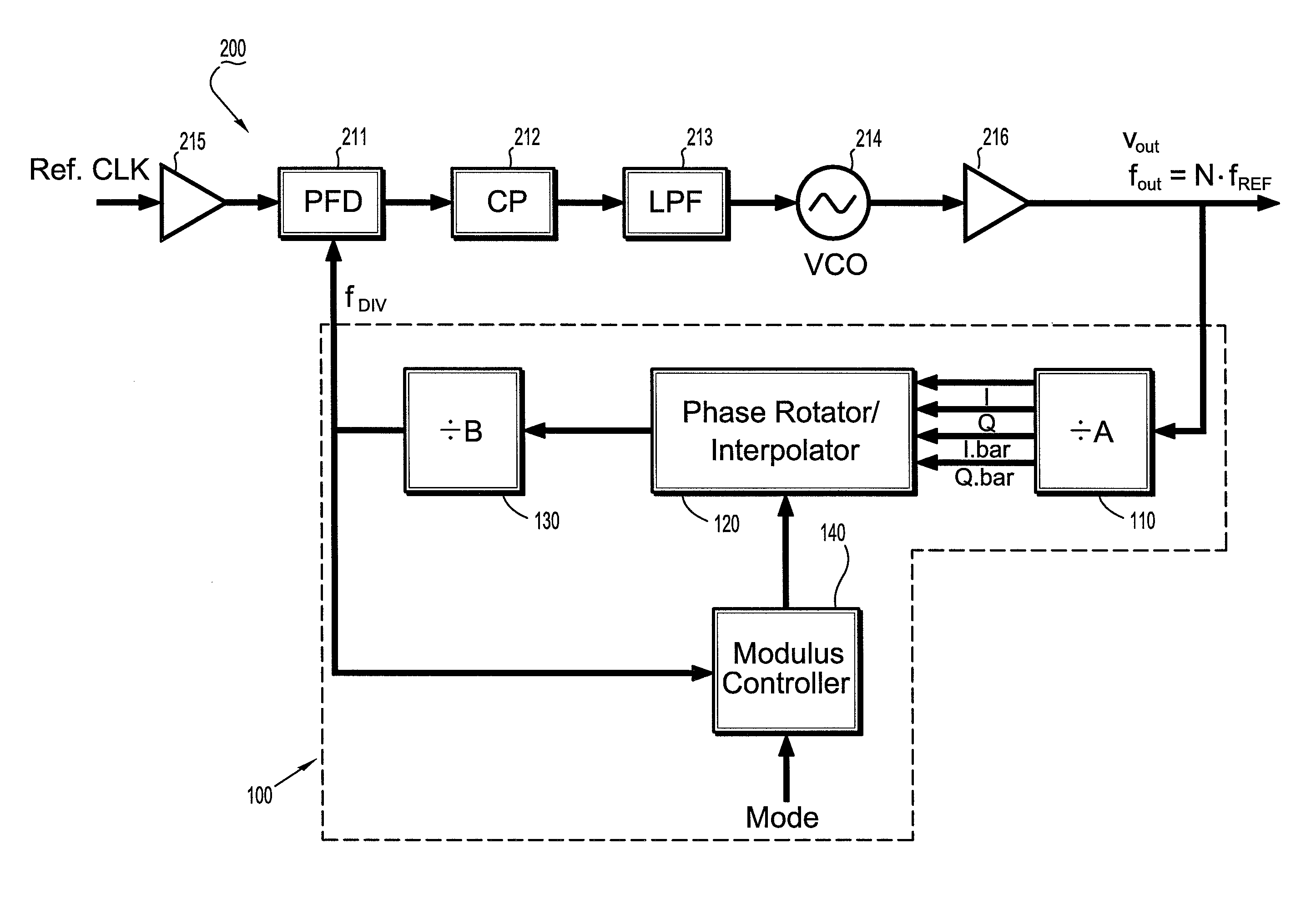
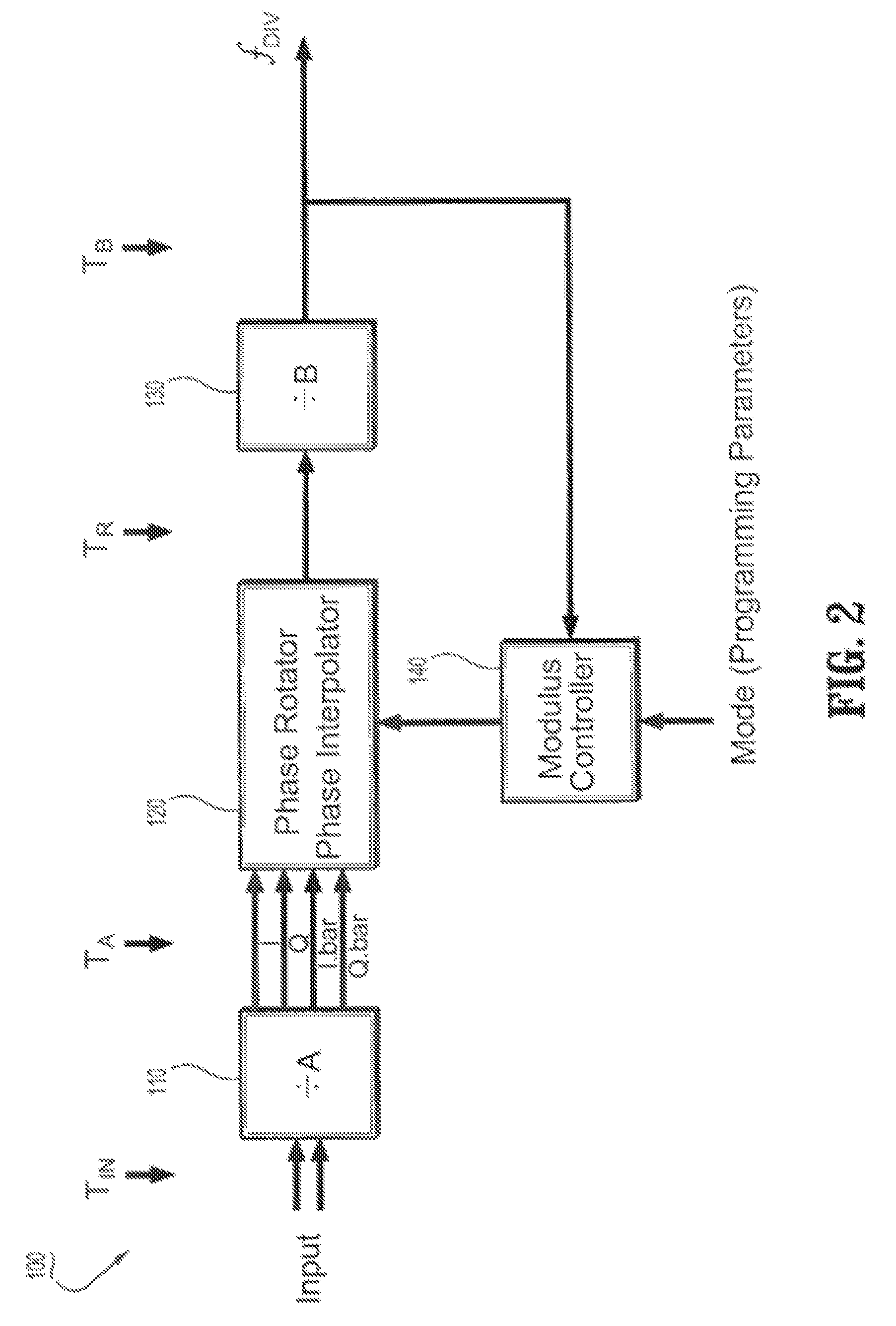
[0044]FIG. 2 is a schematic circuit diagram of a programmable sub-integer N frequency divider circuit (100) according to an exemplary embodiment of the invention. In particular, FIG. 2 schematically illustrates an exemplary framework of a phases switched, rotator-based frequency divider circuit (100) that is designed to generate output signal frequencies having arbitrary fractional (sub-integer) division ratios of an input signal frequency, while eliminating output glitches and minimizing fractional spurs. Sub-integer refers to division ratios of, e.g., X.5, X.25, X.1, etc., where X is an integer. In general, the frequency divider (100) comprises a prescaler (110) with a division ratio (or divisor) A, a phase selector / rotator circuit (120), a post-scaler circuit (130) with a division) ratio B, and a modulus controller (140). The prescaler (110) receives an input signal TIN and divides the input signal TIN by A, where A can be any value, with typical values of 2 or 4. The output sign...


PUM


Abstract

Circuits and methods are provided for implementing programmable sub-integer N frequency dividers for use in, e.g., frequency synthesizer applications, providing glitch free outputs signals with minimal fractional spurs. Phase-rotating sub-integer N frequency dividers are programmable to provide multi-modulus division with a wide range of arbitrary sub-integer division ratios.

Description

GOVERNMENT LICENSE RIGHTS[0001]This invention was made with Government support under Contract No. N66001-02-C-8014 awarded by the Defense Advanced Research Projects Agency (DARPA). The Government has certain rights in this invention.TECHNICAL FIELD OF THE INVENTION[0002]The present invention relates generally to circuits and methods for implementing programmable sub-integer N frequency dividers for use in, e.g., frequency synthesizer applications, and more specifically, phase-switched sub-integer N frequency dividers that are programmable to provide multi-modulus division with a wide range of arbitrary sub-integer division ratios.BACKGROUND[0003]Phase-locked loop (PLL) circuits are critical components commonly implemented in various communications systems to provide, e.g., LO (local oscillator) signals for transceiver circuits, clock signals for data-recovery circuits, etc. In general, a PLL circuit uses feedback to maintain an output signal of the PLL in a specific phase relationsh...

Claims


Application Information

Patent Timeline
Patent Type & Authority Patents(United States)
IPC IPC(8): H03L7/00
CPCH03L7/1974
Inventor FLOYD, BRIAN A.RYLOV, SERGEY V.
Owner INT BUSINESS MASCH CORP
Why Eureka
Try Eureka