Wide band biconical antennas with an integrated matching system

a biconical antenna and matching system technology, applied in the field of antennas, can solve the problems of affecting the elevation pattern, the antenna becomes too long for the desired end use, and the construction suffers at the higher operational end of the useful band,

Active Publication Date: 2005-05-05
SHAKESPEARE CO
View PDF19 Cites 12 Cited by
  • Summary
  • Abstract
  • Description
  • Claims
  • Application Information

AI Technical Summary

Problems solved by technology

Unfortunately, these constructions suffer at the higher operational end of their useful band with natural current nulls and current reversals.
As a result, the antenna becomes too long for the desired end use.
Additionally, the elevation pattern is adversely effected.
An even further increase in frequency results in an elevation pattern bifurcation.
Moreover, as will be seen in the preferred embodiment, the gain va

Method used


Image

  • Wide band biconical antennas with an integrated matching system
  • Wide band biconical antennas with an integrated matching system
  • Wide band biconical antennas with an integrated matching system

Examples


Embodiment Construction

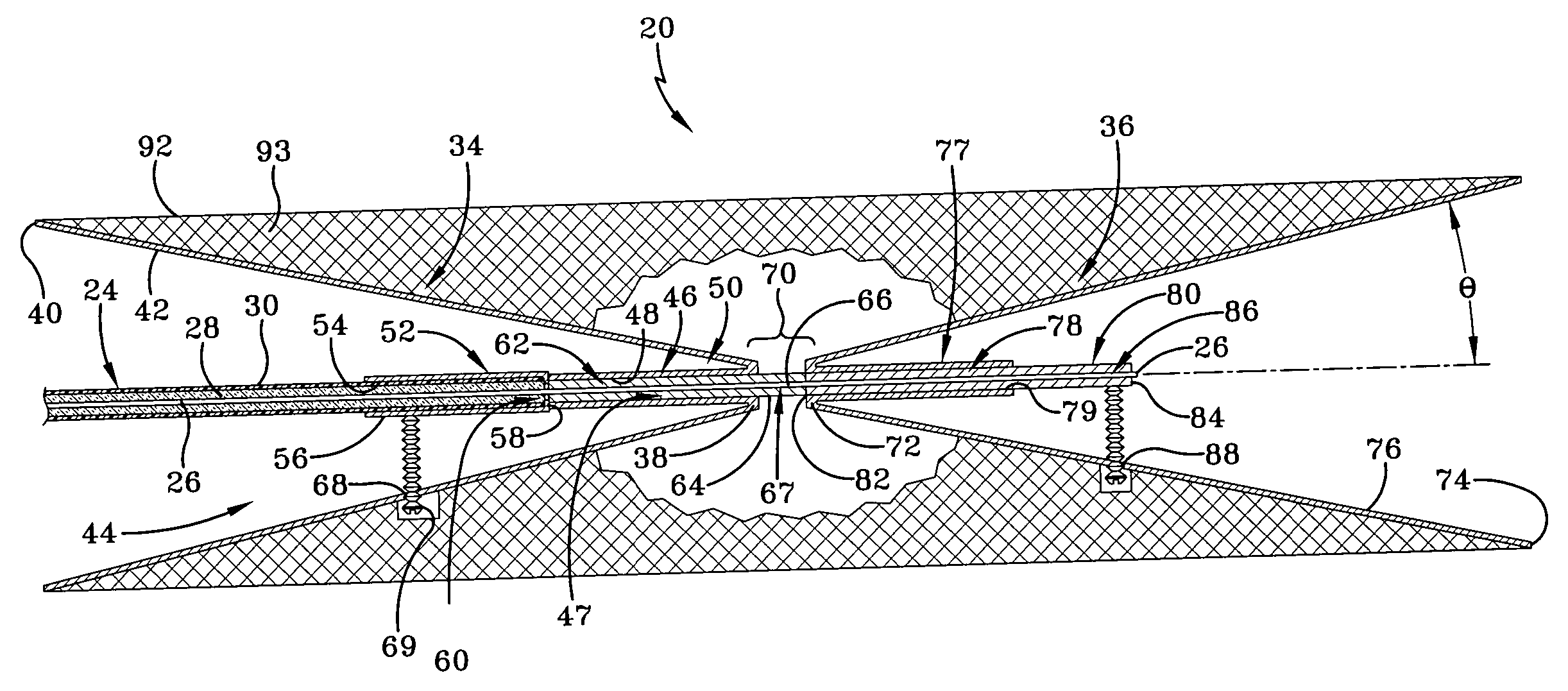
[0024] Referring now to the drawings and, in particular to FIGS. 4 and 4A, a wide band biconical antenna made according to the present invention is designated generally by the numeral20. The antenna 20 is connected to a transmitter / receiver system 22 which may be carried by an individual or vehicle for the purpose of communicating with others. It will be appreciated that the antenna of the preferred embodiment may be employed for ground-to-ground or ground-to-air communications and even potentially satellite communications with asymmetrical conic sections.

[0025] The transmitter / receiver 22 is connected to the antenna 20 by a transmission line 24. In the preferred embodiment, the transmission line is a 50 ohm coaxial cable, one end of which extends into the antenna 20 and is terminated in a manner to be discussed in detail. The transmission line 24 includes a center conductor 26 that is surrounded by a dielectric insulation material 28. A conductive shield 30, which is preferably a ...


PUM


Abstract

A biconical antenna; an entry conic having an entry base opposite an entry vertex and a termination conic having a termination base opposite a termination vertex. The entry and termination conics share substantially the same axis and the entry vertex is adjacent the termination vertex. The transmission line is received by the entry conic and terminated in the termination conic. Together, the entry conic and the termination conic phase correct energy emanating from the transmission line. Another embodiment of the antenna comprises an entry conic having at least two sub-conics and a termination conic having at least two sub-conics. Each of the sub-conics having an integer multiple of a half-angle. The biconical antenna may also include a multi-conductor transmission line, wherein the biconical antennas are arranged in a co-linear relationship. Each of the multi-conductors is coupled to at least one of the plurality of biconical antennas.

Description

TECHNICAL FIELD [0001] The present invention relates generally to antennas used in mobile and / or military applications. More particularly, the present invention relates to a biconical antenna with an instantaneous bandwidth of about 500-2500 MHz with a relatively low Voltage Standing Wave Ratio (VSWR) and high gain. Specifically, the present invention provides a biconic antenna with a matching system in one of the conics and wherein the biconics have a relatively low-angle configuration. BACKGROUND ART [0002] It is known that electromagnetic communication systems employ broad bandwidth techniques, such as the so-called frequency-agile or frequency-hopping systems in which both the transmitter and receiver rapidly and frequently change communication frequencies within a broad frequency spectrum in a manner known to both units. When operating with such systems, antennas having multiple matching and / or tuning circuits must be switched, whether manually or electronically, with the insta...

Claims


Application Information

Patent Timeline
IPC IPC(8): H01Q1/24H01Q5/00H01Q9/28H01Q13/04
CPCH01Q1/241H01Q13/04H01Q9/28
Inventor MARTEK, GARY A.
Owner SHAKESPEARE CO
Why Eureka
Try Eureka