Liquid crystal display device, driving circuit for the same and driving method for the same

a technology of liquid crystal display device and driving circuit, which is applied in the direction of instruments, static indicating devices, etc., can solve the problems that the display quality cannot be improved, and achieve the effect of favorable display quality, suppressing flicker, and suppressing flicker

Inactive Publication Date: 2005-05-05
SHARP KK
View PDF4 Cites 46 Cited by
  • Summary
  • Abstract
  • Description
  • Claims
  • Application Information

AI Technical Summary

Benefits of technology

[0012] It is thus an object of the present invention to provide a liquid crystal display device with which flickering caused by the polarity change pattern itself can be suppressed and a favorable display quality can be attained, as well as a driving circuit and a driving method for the same.
[0017] With this configuration, for every predetermined number of frame periods, the number of times that the polarity of the pixel voltage of each of the pixel formation portions becomes positive is the same as the number of times that it becomes negative. Thus, the polarity of the pixel voltage of each of the pixel formation portions does not display a preference towards positive or negative. Therefore, it is possible to suppress flickering without deteriorating the liquid crystal, with a configuration in which the polarity of the pixel voltage of each of the pixel formation portions is changed without regularity.
[0021] With this configuration, a plurality of polarity pattern tables indicating the polarities of the pixel voltages for all of the pixel formation portions within one block into which a predetermined number of scanning signal lines have been grouped together are stored in advance. Then, voltages are applied to the pixel formation portions, in accordance with polarity pattern tables that are selected irregularly. Thus, by repeating, in the direction in which the video signal lines extend on the display screen, the same polarity pattern as the polarity pattern represented by the polarity pattern table for a given block, it is possible to let the polarities of the pixel voltages of all pixel formation portions on the display screen change without regularity. Moreover, within a predetermined period, the polarity pattern tables are selected once each. Thus, the polarities of the pixel voltages of all pixel formation portions do not display a preference towards positive or negative. Therefore, it is easy to suppress flickering without deteriorating the liquid crystal.
[0023] With this configuration, the polarities of pixel voltages of a plurality of pixel formation portions that are consecutive in a direction in which the video signal lines extend on the display screen are inverted at intervals of the plurality of pixel formatin portions with the same polarity. Thus, insufficient charging of the pixel capacities, which may occur when the polarities of the pixel voltages are inverted at every line, can be prevented, and also the power consumption is reduced.

Problems solved by technology

Thus, the degradiation of the display quality could not be prevented.

Method used


Image

  • Liquid crystal display device, driving circuit for the same and driving method for the same
  • Liquid crystal display device, driving circuit for the same and driving method for the same
  • Liquid crystal display device, driving circuit for the same and driving method for the same

Examples


example 1

5.1 Modified Example 1

[0084] In the above-described embodiment, each of the bits of the polarity instruction bit data REVd obtained from the look-up table 5 indicates the polarities of a given row (one scanning signal line), but the present invention is not limited to this. The bits may also indicate the polarities of a plurality of rows. The following is a description of the case that each of the bits of the look-up table 5 shown in FIG. 5 indicates the polarity for two rows. If the random number generation circuit 4 outputs random numbers N in a similar order as in the case shown in FIG. 3 described in the foregoing embodiment, then the polarity change pattern becomes as shown in FIG. 9. In FIG. 9, the polarities in the direction in which the video signal lines extend change such that positive polarities as well as negative polarities are continuous for at least two rows. Thus, with a configuration in which one bit of the polarity instruction bit data REVd represents the polarity ...

example 2

5.2 Modified Example 2

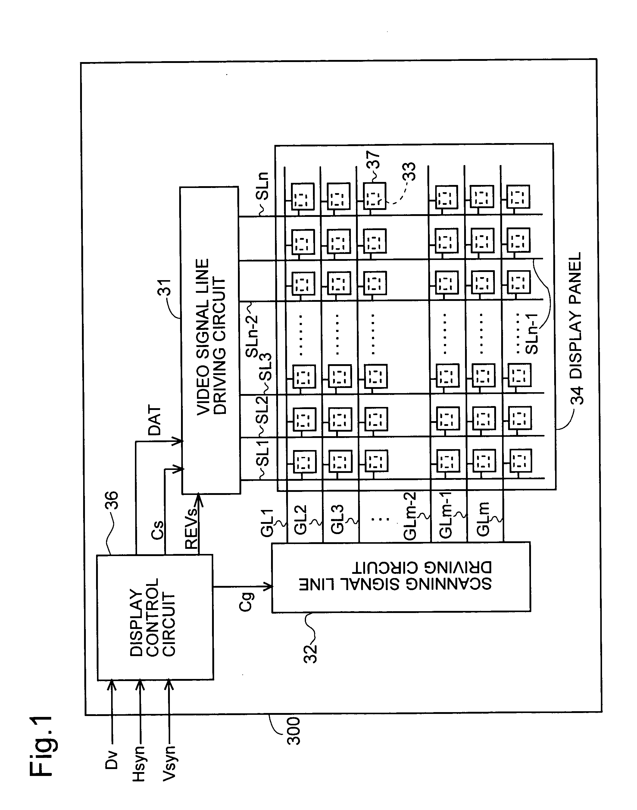
[0085] Moreover, the above-described embodiment was explained for an example of dot inversion driving in which the polarity is inverted at every column, in the direction in which the scanning signal lines extend on the display screen, but the present invention is not limited to this, and can also be applied to line inversion driving. FIGS. 10A to 10D are diagrams showing an example of the order in which polarity patterns are generated in each frame period within one polarity equilibrium period in this modified example. FIG. 10A shows the polarity of the pixel formation portions 37 in the first frame period. FIG. 10B shows the polarity of the pixel formation portions 37 in the second frame period. FIG. 10C shows the polarity of the pixel formation portions 37 in the third frame period. FIG. 10D shows the polarity of the pixel formation portions 37 in the fourth frame period. In FIGS. 10A to 10D, the pixel formation portions 37 extending in the horizontal directi...

example 3

5.3 Modified Example 3

[0086] Furthermore, in the above-describe embodiment, in order to ensure that the polarity pattern tables stored in the look-up table 5 are selected once each within per polarity equilibrium period, the random number generation circuit 4 is configured such that a number of different numbers that is the same as the number of polarity pattern tables stored in the look-up table 5 is outputted once each per polarity equilibrium period, but the present invention is not limited to this. FIG. 11 is a diagram showing a look-up table 5 according to this modified example. Compared to the look-up table 5 in FIG. 5, a column denoted “BitR” has been added. When the liquid crystal display device is started up, a “0” is stored in BitR of each of the rows of the look-up table 5 shown in FIG. 11. Then, when a polarity pattern table is selected based on a random number N that is outputted by the random number generation circuit 4, the BitR of the row denoting the selected polari...


PUM

PropertyMeasurementUnit
voltageaaaaaaaaaa
polarityaaaaaaaaaa
polaritiesaaaaaaaaaa

Abstract

A look-up table stores a plurality of polarity pattern tables for setting the polarities of pixel voltages of pixel formation portions on a display screen. The plurality of polarity pattern tables are set such that when each of the polarity pattern tables is selected once, the number of positive polarities appearing at each of the pixel formation portions is the same as the number of negative polarities. The polarity instruction signal generation circuit selects one of the polarity pattern tables based on a random number that is outputted from a random number generation circuit, and outputs a polarity instruction signal based on the selected polarity pattern table. Then, the video signal line driving circuit outputs video signals such that a voltage with a polarity in accordance with the polarity instruction signal is applied to each of the pixel formation portions.

Description

CROSS REFERENCE TO RELATED APPLICATIONS [0001] This application claims priority under 35 U.S.C. § 119(a) upon Japanese Patent Application No. 2003-375328 titled “LIQUID CRYSTAL DISPLAY DEVICE, DRIVING CIRCUIT AND DRIVING METHOD FOR THE SAME,” filed on Nov. 5, 2003, the entire content of which is hereby incorporated by reference. BACKGROUND OF THE INVENTION [0002] 1. Field of the Invention [0003] The present invention relates to driving circuits and driving methods of liquid crystal display devices, and in particular to the polarity inversion of voltages applied to pixels in active matrix liquid crystal display devices. [0004] 2. Description of the Related Art [0005] Active matrix liquid crystal display devices provided with TFTs (thin film transistors) as switching elements have been known for several years. Such liquid crystal display devices are provided with a liquid crystal panel which includes two insulating substrates that are arranged opposite one another. On one substrate of...

Claims


Application Information

Patent Timeline
Patent Type & Authority Applications(United States)
IPC IPC(8): G02F1/133G09G3/20G09G3/36
CPCG09G3/2092G09G2320/0247G09G2320/0204G09G3/3614G09G3/36
Inventor HOSOTANI, YUKIHIKO
Owner SHARP KK
Why Eureka
Try Eureka