
Video recording method, video recording apparatus, video recording medium, video display method, and video display apparatus

a video recording and display technology, applied in the field of video recording methods, can solve problems such as difficulty in perfect following the brightness change of the light adjustment state, white compression of the displayed image, and flicker of the video

Inactive Publication Date: 2005-05-05
SEIKO EPSON CORP
View PDF10 Cites 7 Cited by
  • Summary
  • Abstract
  • Description
  • Claims
  • Application Information

AI Technical Summary

Benefits of technology

[0012] Thus, the image signal and the light adjustment control signal can be recorded in association with each other to the video recording medium in advance. Therefore, when reproducing the video signal from the video recording medium, the image signal and the quantity of light adjustment by the light adjusting device can be prevented from becoming asynchronous, and occurrence of white compression or flicker in the reproduced video can be prevented. Moreover, the light adjustment control signal enables reproduction of the video in a light quantity state intended by the video producer.
[0020] Thus, the image signal and the light adjustment control signal can be recorded in association with each other to the video recording medium in advance. Therefore, when the video display apparatus reproduces the video from the video recording medium, the video and the quantity of light adjustment can be prevented from becoming asynchronous, and occurrence of white compression or flicker in the reproduced video can be prevented. Moreover, the light adjustment control signal enables reproduction of the video in a light quantity state intended by the video producer.
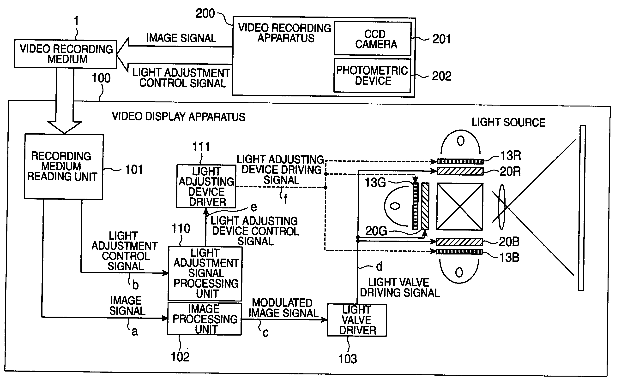
[0024] A video recording medium according to this invention is a video recording medium to be reproduced by a video display apparatus that changes an image on a light valve in accordance with an input image signal and changes the quantity of light to be incident on the light valve by a light adjusting device. The video recording medium having a light adjustment control signal for controlling the light adjusting device that is recorded therein together with and synchronously with the image signal. With such a structure, information on the brightness of the image (for example, maximum value or average value of gradation of brightness of the image) is recorded as a light adjustment control signal to a video recording medium such as DVD-ROM synchronously with the image signal. Then, when a video display apparatus having a light valve and a light adjusting device reproduces the image signal from this video recording medium, the quantity of light adjustment is controlled by the light adjusting device synchronously with the image by the light adjustment control signal recorded on the video recording medium. Thus, the image signal and the light adjustment control signal can be recorded in association with each other to the video recording medium in advance. Therefore, when the video display apparatus reproduces the video from the video recording medium, the video and the quantity of light adjustment can be prevented from changing asynchronously, and occurrence of white compression or flicker in the reproduced video can be prevented. Moreover, the light adjustment control signal enables reproduction of the video in a light quantity state intended by the video producer.
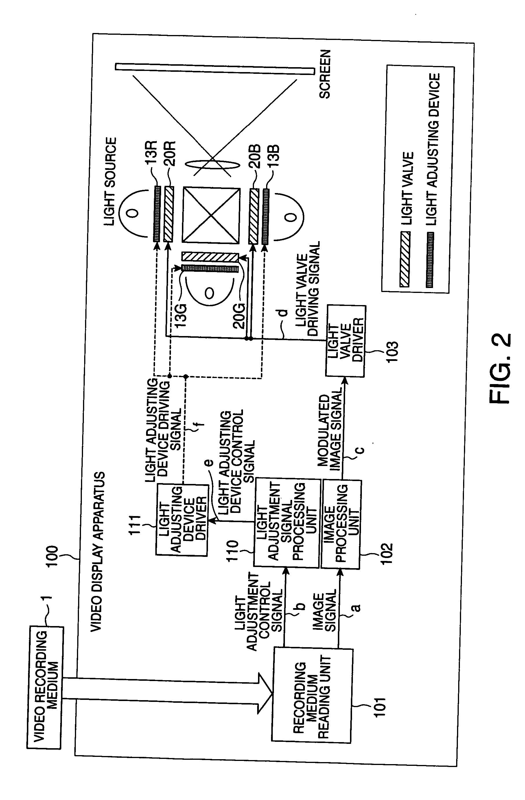
[0029] In such a method, when reproducing the image signal recorded on the video recording medium, the video display apparatus reads out the light adjustment control signal recorded in advance in association with the image signal and controls the quantity of light adjustment by the light adjusting device synchronously with the image signal to be reproduced, on the basis of the light adjustment control signal. Thus, when the video display apparatus reproduces the image signal, the video and the quantity of light adjustment can be prevented from becoming asynchronous, and occurrence of white compression or flicker in the reproduced video can be prevented.
[0030] The video display method according to this invention is also characterized in that the light adjustment control signal can include white balance information, and that after shooting light source color information representing the color of light source at the movie-shooting is acquired on the basis of the white balance information, correction light source information for canceling and correcting the shooting light source color information to reference point color information representing reference color information is calculated, and on the basis of the correction light source information, the quantity of light of the light adjusting device is controlled synchronously with the image signal to be reproduced. Thus, for example, if the color of the shot video becomes greenish shot, the color of light source is corrected to magenta color on the basis of the correction light source information. Therefore, the color perceived at the time of actual shooting can be realized faithfully.
[0033] With such a structure, when reproducing the image signal recorded on the video recording medium, the video display apparatus reads out the light adjustment control signal recorded in advance in association with the image signal and controls the quantity of light adjustment by the light adjusting device synchronously with the image signal to be reproduced, on the basis of the light adjustment control signal. Thus, when the video display apparatus reproduces the image signal, the video and the quantity of light adjustment can be prevented from changing asynchronously, and occurrence of white compression or flicker in the reproduced video can be prevented.

Problems solved by technology

However, in general videos of movie, television and the like, the brightness of the image varies, and it is difficult for the light adjustment state to perfectly follow the changes in the brightness.
As a result, problems arise such as occurrence of white compression in the displayed image and flicker of the video.
For example, in an example shown in FIG. 8(a), response of light adjustment control is slow and cannot follow changes in videos, thus causing white compression.
Therefore, hunting and flicker of the image can occur.
However, also in the method disclosed, it can be difficult for the light adjustment state to perfectly follow the brightness of the image.

Method used


Image

  • Video recording method, video recording apparatus, video recording medium, video display method, and video display apparatus
  • Video recording method, video recording apparatus, video recording medium, video display method, and video display apparatus
  • Video recording method, video recording apparatus, video recording medium, video display method, and video display apparatus

Examples


Embodiment Construction

[0047] Exemplary embodiments for carrying out this invention will now be described with reference to the drawings.

[0048] First, an exemplary video display apparatus according to this invention will be described.

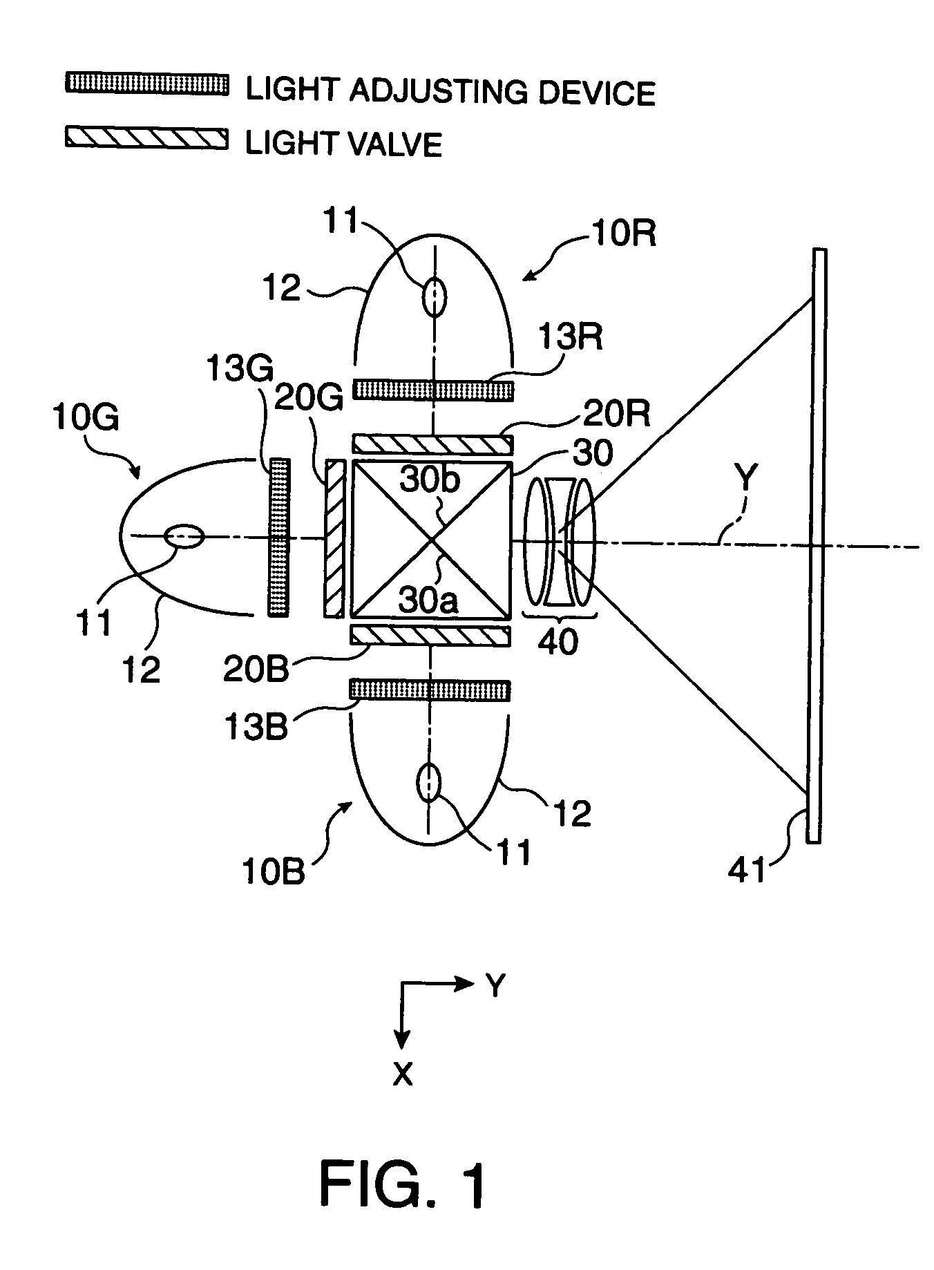
[0049]FIG. 1 shows a display unit of a projection-type video display apparatus to which this invention is applied. It is an example of three-plate projection-type color video display apparatus having light valves (liquid crystal light valves or the like) that transmit different colors such as R (red), G (green) and B (blue), respectively. In FIG. 1, numerals 10R, 10G, 10B denote light sources, 13R, 13G, 13B denote light adjusting devices, 20R, 20G, 20B denote light valves (liquid crystal light valves), 30 denotes a cross dichroic prism, 40 denotes a projection lens, and 41 denotes a screen.

[0050] The light sources 10R, 10G, 10B are color light sources capable of emitting red light, green light, and blue light, respectively. Each of the light sources 10R, 10G, 10B is formed...


PUM

PropertyMeasurementUnit
transmittanceaaaaaaaaaa
brightnessaaaaaaaaaa

Abstract

Aspects of the invention can provide a video recording method that can reduce or prevent occurrence of white compression or flicker at the reproduction of an image in a projection-type video display apparatus using a light valve and a light adjusting device. In the video recording method for recording a video to a video recording medium used in a video display apparatus that changes an image on a light valve in accordance with an input image signal and changes the quantity of light to be incident on the light valve by a light adjusting device, when recording an image signal to the video recording medium, a light adjustment control signal for controlling the light adjusting device can be recorded synchronously with the image signal.

Description

BACKGROUND OF THE INVENTION [0001] 1. Field of Invention [0002] Aspects of the invention can relate to a video recording method, a video recording apparatus, a video recording medium, a video display method, and a video display apparatus, and particularly to a video recording method, a video recording apparatus, a video recording medium, a video display method, and a video display apparatus in which flicker or white compression of an image (also referred to as video in this specification) does not occur when reproducing an image signal recorded on a video recording medium by using a projection-type video display apparatus. [0003] 2. Description of Related Art [0004] Related information apparatuses have greatly evolved, and display apparatuses having higher resolution, consuming less power and having reduced thickness have been increasingly demanded. Particularly, liquid crystal display apparatuses are expected to be display apparatuses capable of meeting the above-described demand b...

Claims


Application Information

Patent Timeline
Patent Type & Authority Applications(United States)
IPC IPC(8): G03B21/00G02B27/18G02B27/28G02F1/133G03B21/20G09G3/20G09G3/34G09G3/36G09G5/02H04N5/30H04N5/66H04N5/74H04N5/77H04N5/85H04N5/91H04N9/31H04N9/73H04N9/804H04N9/82
CPCH04N5/77H04N5/772H04N9/8205H04N9/73H04N9/8042H04N5/85G03B21/00G03B21/20G02B27/28
Inventor YOSHIDA, SHOHEI
Owner SEIKO EPSON CORP
Learn More