Two-piece magnetic shield having improved heat dissipation

a magnetic shield and two-piece technology, applied in the field of magnetic shields, can solve the problems of damage to the read head, and failure to meet the needs of use, and achieve the effect of improving heat dissipation and less field disturban

Active Publication Date: 2005-05-05
HEADWAY TECH INC
View PDF6 Cites 11 Cited by
  • Summary
  • Abstract
  • Description
  • Claims
  • Application Information

AI Technical Summary

Benefits of technology

[0009] These objects have been achieved by dividing the bottom shield into two pieces both of which sit on top of a non-magnetic heat sink. Heat generated by the coil during a writing process is transferred to the non-magn

Problems solved by technology

However, there are many reliability problems associated with this low fly height.
Problems such as thermal pole tip protrusion, resulting from thermal mismatch between the alumina and pole materia

Method used


Image

  • Two-piece magnetic shield having improved heat dissipation
  • Two-piece magnetic shield having improved heat dissipation
  • Two-piece magnetic shield having improved heat dissipation

Examples


Embodiment Construction

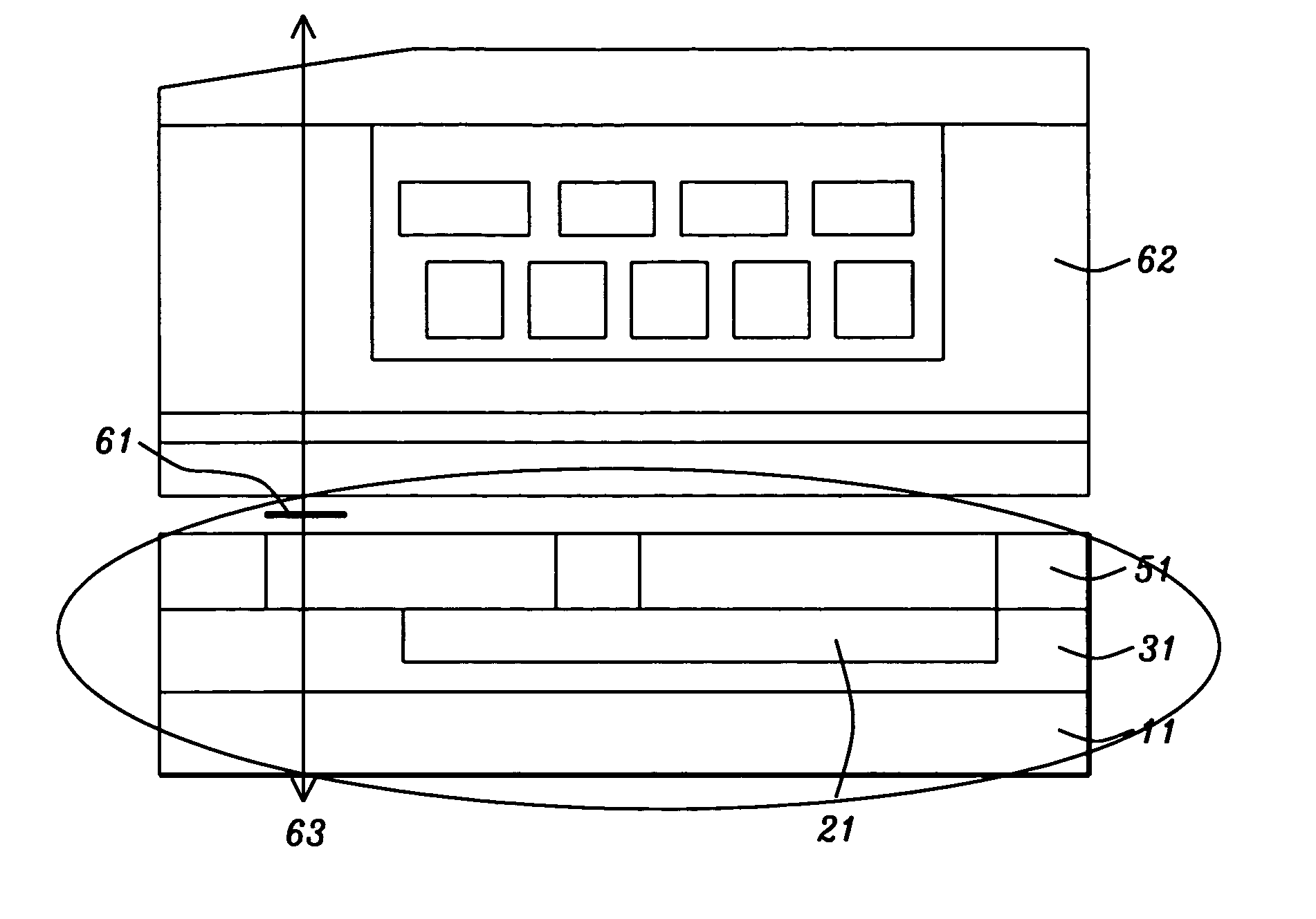
[0015] The present invention teaches a novel method to make a two-piece bottom shield with both pieces sitting on top of a non-magnetic metal heat sink. The heat generate by the coil during writing is transferred to the non-magnetic metal heat sink and hence transfers to the substrate. With this approach, the head not only benefits from less field disturbance (due to the small shield) but also receives improved the heat dissipation from the additional heat sink We will disclose the invention through a description of the process for manufacturing a read-write head that includes the key novel features of the invention, namely the split shield underlaid by a heat sink. Said process description will also serve to make clear the structure of the present invention.

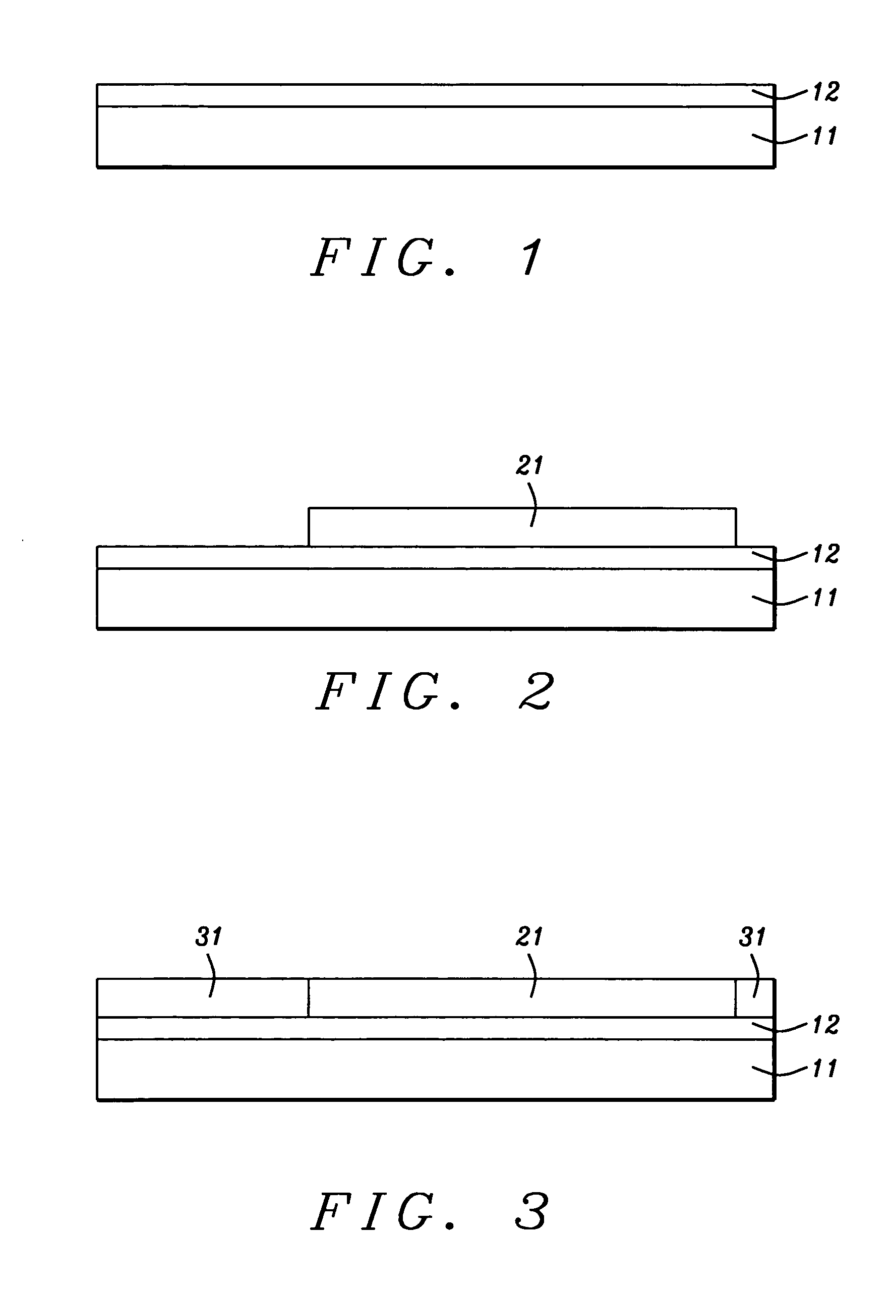
[0016] Referring now to FIG. 1, the process of the present invention begins with the provision of substrate 11 and then depositing thereon dielectric layer 12. Then layer of non-magnetic material 21, having a thermal conductivi...


PUM

PropertyMeasurementUnit
Lengthaaaaaaaaaa
Lengthaaaaaaaaaa
Thicknessaaaaaaaaaa

Abstract

Problems such as thermal pole tip protrusion result from thermal mismatch between the alumina and pole material during the writing process. This, and similar problems due to inadequate heat dissipation, have been overcome by dividing the bottom shield into two pieces both of which sit on top of a non-magnetic heat sink. Heat generated by the coil during writing is transferred to the non-magnetic heat sink whence it gets transferred to the substrate. With this approach, the head not only benefits from less field disturbance due to the small shield but also improves heat dissipation from the additional heat sink

Description

FIELD OF THE INVENTION [0001] The invention relates to the general field of magnetic heads with particular reference to dissipating heat in accompanying magnetic shields. BACKGROUND OF THE INVENTION [0002] For high areal density magnetic recording, one of the requirements is to have lower fly height in order to have better signal to noise ratio for better head performance. However, there are many reliability problems associated with this low fly height. Problems such as thermal pole tip protrusion, resulting from thermal mismatch between the alumina and pole material during the writing process will create a head disk interface problem and eventually damage the read head. [0003] One way to reduce thermal pole tip protrusion is to have a better heat dissipation mechanism so that heat generated by the coil during the writing process can be transferred to the substrate to avoid heat accumulation. On the other hand, it is required to have a small shield that only covers the read sensor (...

Claims


Application Information

Patent Timeline
IPC IPC(8): G11B5/127G11B5/31G11B5/33
CPCG11B5/3133G11B5/3136Y10T29/49043Y10T29/49039Y10T29/49048Y10T29/49046Y10T29/49052
Inventor HAN, CHERNG-CHYILEE, RODCHEN, MAO-MINWANG, POKANG
Owner HEADWAY TECH INC
Why Eureka
Try Eureka