Vehicular headlamp
a headlamp and headlamp technology, applied in the field of headlamps, can solve the problems of reducing the ability to achieve thin formation of lamp pieces by adopting semiconductor light emitting elements as light sources, unable to prolong the luminous intensity distribution pattern sideways, etc., to achieve the effect of preventing glare against the driver of a car running on the opposite lane, promoting indirect illumination effect of lamp pieces, and effective restraint of non-uniform luminous intensity distribution
- Summary
- Abstract
- Description
- Claims
- Application Information
AI Technical Summary
Benefits of technology
Problems solved by technology
Method used
Image
Examples
first embodiment
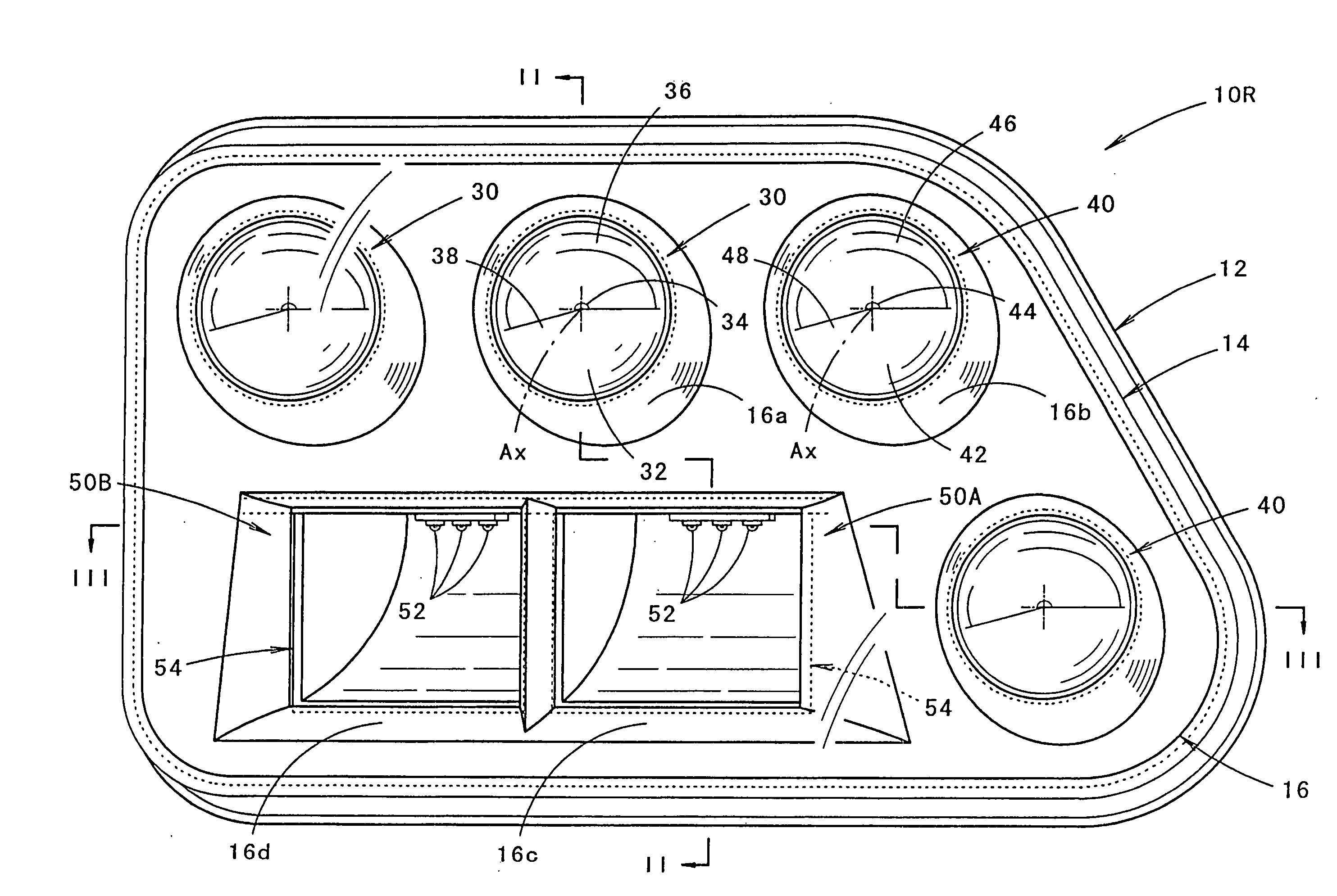
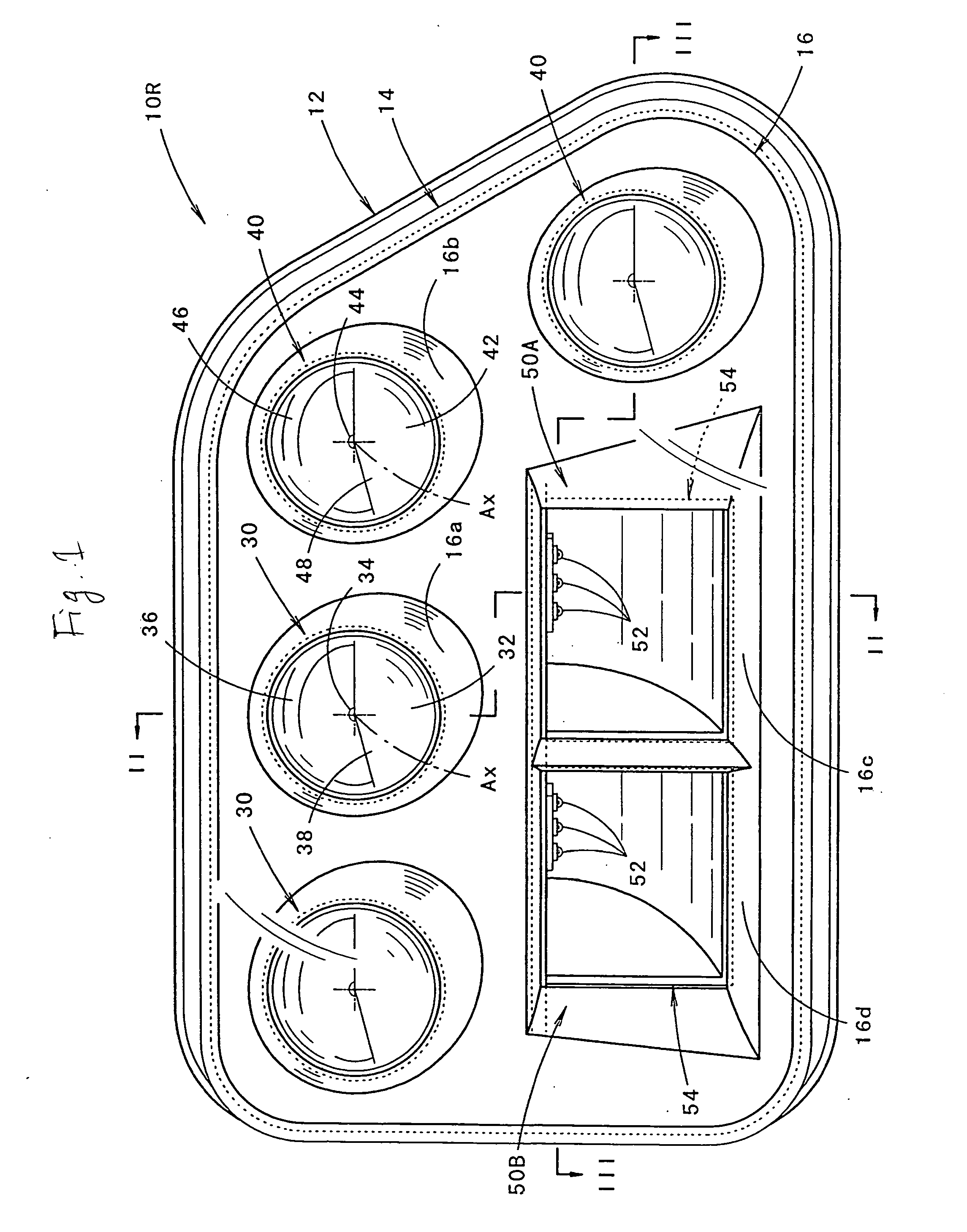
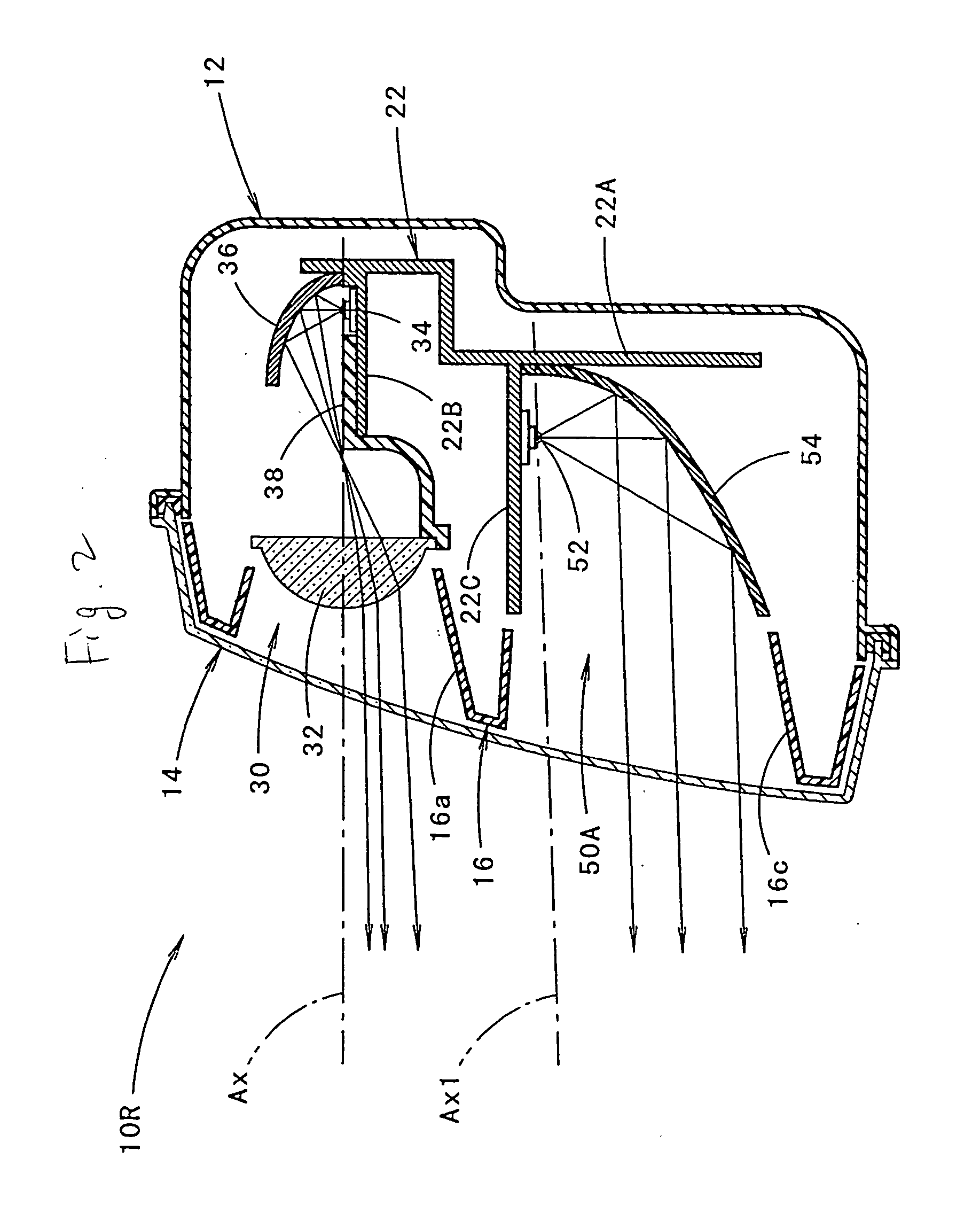
[0081] As described above, the luminous intensity distribution pattern PL for low beam is formed by irradiating light from the six lamp piece units 30, 40, 50A, 50B constituting light sources of the semiconductor light emitting elements. Of the six lamp piece units, other than the four front irradiating lamp piece units 30, 40, two side irradiating lamp piece units 50A, 50B are provided. The respective side irradiating lamp piece units 50A, 50B are constituted as the lamp piece units of the parabolic pillar type. Therefore, the luminous intensity distribution patterns PL 3A, PL 3B that are prolonged sideways can be formed by irradiated light thereof to enable easy formation of the wide diffusing region of the luminous intensity distribution pattern PL for the low beam.
[0082] In this case, the lamp piece units 50A, 50B of the parabolic pillar type are constituted as the side irradiating lamp piece units. Therefore, when the surface shape of the vehicular headlamp 10R is flexed to th...
second embodiment
[0095]FIG. 14 is a perspective view showing a luminous intensity distribution pattern for a low beam formed on the imaginary vertical screen by light irradiated from the vehicular headlamp 10L to a front direction.
[0096] The luminous intensity distribution pattern PL for low beam is substantially similar to the case of the luminous intensity distribution pattern PL for low beam shown in FIG. 10 with regard to the luminous intensity distribution patterns PL 1, PL 2 formed by irradiating light from the front irradiating lamp piece units 30, 40. However, with regard to the luminous intensity distribution patterns PL 3A, PL 3B formed by irradiating light from the side irradiating lamp piece units 50A, 50B, the luminous intensity distribution pattern PL for low beam is brought into a positional relationship symmetric with the luminous intensity distribution pattern PL for low beam of FIG. 10 in the left and right direction.
[0097] Also in the second embodiment, although the surface shap...
PUM
 Abstract
Description
Claims
Application Information
 - R&D
- Intellectual Property
- Life Sciences
- Materials
- Tech Scout
- Unparalleled Data Quality
- Higher Quality Content
- 60% Fewer Hallucinations
Browse by: Latest US Patents, China's latest patents, Technical Efficacy Thesaurus, Application Domain, Technology Topic, Popular Technical Reports.
© 2025 PatSnap. All rights reserved.Legal|Privacy policy|Modern Slavery Act Transparency Statement|Sitemap|About US| Contact US: help@patsnap.com


