Method and apparatus for detecting the location and luminance transition range of slant image edges

a technology of luminance transition and slant image edge, which is applied in the field of image detail enhancement, can solve the problems of poor image quality, zigzag edge artifacts of slant image edge, and visual quality degradation, so as to reduce complexity, facilitate processing, and improve detection process speed

Inactive Publication Date: 2005-05-05
SAMSUNG ELECTRONICS CO LTD
View PDF5 Cites 11 Cited by
  • Summary
  • Abstract
  • Description
  • Claims
  • Application Information

AI Technical Summary

Benefits of technology

[0010] In the Slant Edge Center Locator, the values of the current pixel and its neighboring pixels inside said rectangular window are used to determine if the selected pixel is the center pixel in a luminance transition range of a slant edge. More specifically, the value of each pixel inside the window is compared with the luminance mean value of all the pixels inside the window, and only the comparison results are used in the succeeding detection process. To facilitate the processing, such comparison results can be saved as binary pattern data for each pixel in the window through a binary pattern data generator in the Slant Edge Center Locator. The binary pattern data essentially serve as a buffer for saving some intermediate results, and is therefore optional. However, using the binary pattern data helps reduce the complexity and improves the speed of the detection process at the expense of a little more memory.

Problems solved by technology

An instance of such visual quality degradation is a zigzagged edge artifact due to conventional image detail enhancement.
However, some artifacts can also be introduced into image edges because of the enhancement.
As a result, even though the image in FIG. 1B is enhanced, the quality of the image looks poor due to the degradation of edge quality.
Otherwise, a slant image edge can develop zigzagged edge artifacts if it is enhanced substantially.

Method used


Image

  • Method and apparatus for detecting the location and luminance transition range of slant image edges
  • Method and apparatus for detecting the location and luminance transition range of slant image edges
  • Method and apparatus for detecting the location and luminance transition range of slant image edges

Examples


Embodiment Construction

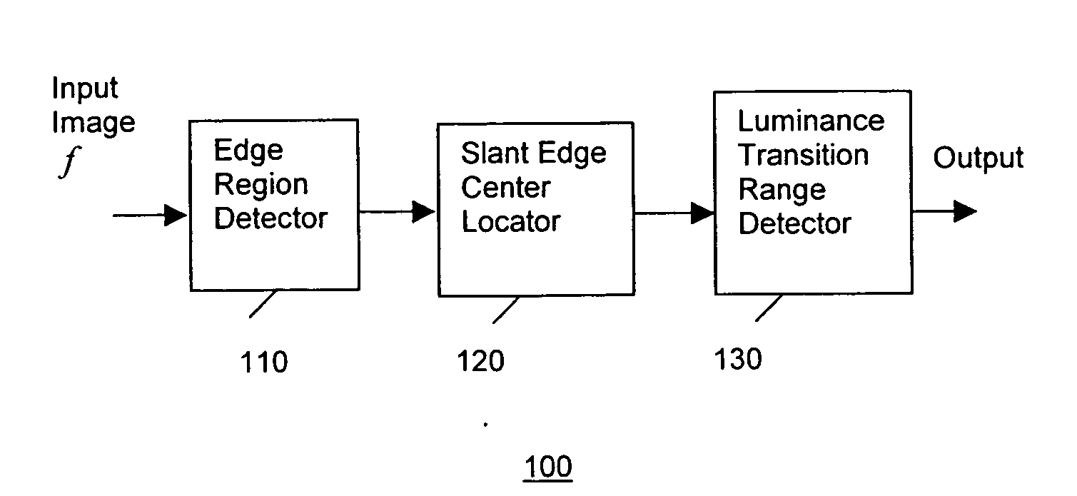
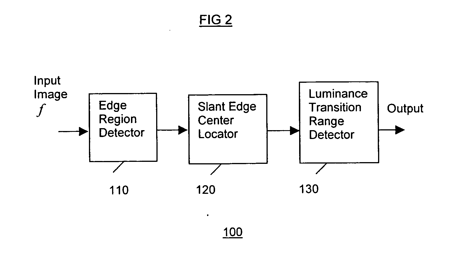
[0022] The present invention addresses the above needs. In one embodiment, the present invention provides a method for detecting the location and luminance transition range of slant image edges in a digital image, so that pixels belonging to each slant edge can be processed separately / differently than other image pixels.

[0023] As noted, in one implementation, the detection method is conducted on a pixel basis, wherein each pixel is checked together with its neighboring pixels inside a rectangular window centered with the current pixel. The variance value of the pixels inside the rectangular window centered with a current pixel is checked to determine if the current pixel is in an edge region or in a non-edge region. If the current pixel is in an edge region, then the value of each pixel inside the rectangular window is compared with the mean value of the all the pixels inside the window. Only the comparison results are used in the succeeding detection process. To facilitate the pro...


PUM


Abstract

A system that detects the location as well as the luminance transition range of slant image edge in a digital image. The variance value of the pixels inside a rectangular image window centered with a current pixel is checked to determine if the current pixel is in an edge region or a in non-edge region. If the current pixel is in a non-edge region, no further checking is performed. Otherwise, it is determined if the current pixel is a center pixel in a luminance transition range of a slant edge. The values of the current pixel and its neighboring pixels inside the rectangular window are used to determine if the selected pixel is the center pixel in a luminance transition range of a slant edge. If it is, then the exact length of the luminance transition range of the slant edge is determined. Through such a detection process, both the center position and the luminance transition range of slant image edge can be determined.

Description

FIELD OF THE INVENTION [0001] The present invention relates to image detail enhancement, and in particular, to detecting the location as well as the luminance transition range of slant image edges in digital images. BACKGROUND OF THE INVENTION [0002] In digital image systems (such as digital TV systems), in order to boost video quality, images are often enhanced in many different aspects, such as image details, image contrast, etc., before being displayed. For a digital image, the quality of edges in the image (i.e., image edges) are of great importance to the overall image quality. Therefore, during the enhancement processes, each image edge should be well preserved. In other words, image enhancement should not sacrifice image edge quality. Otherwise, the overall visual quality of the image may be degraded even though the image is enhanced in certain aspects. [0003] An instance of such visual quality degradation is a zigzagged edge artifact due to conventional image detail enhancem...

Claims


Application Information

Patent Timeline
Patent Type & Authority Applications(United States)
IPC IPC(8): H04N5/208G06K9/00G06K9/48G06T5/00H04N5/14
CPCG06T7/0022H04N5/142G06T2207/10016G06T7/0083G06T7/12G06T7/97H04N5/208
Inventor WANG, XIANGLINKIM, YEONG-TAEG
Owner SAMSUNG ELECTRONICS CO LTD
Why Eureka
Try Eureka