Optical filber cable suitable for installation using an air-blown installation method

Active Publication Date: 2005-05-05
SAMSUNG ELECTRONICS CO LTD
8 Cites 22 Cited by

AI-Extracted Technical Summary

Problems solved by technology

However, such installing methods may apply excessive stress to the optical fiber cable causing damage.
This is therefore a design limitation for the optical fiber cables.
However, if the optical fiber cable using with the air-blown installation method is designed identically...

Benefits of technology

[0012] Another aspect of the present invention is an optical fiber cable having a lighter weight with a reduced number of comp...

Abstract

An optical fiber cable suitable installation using an air-blown method is disclosed. The optical fiber cable has a center tensile member located at a center of the optical fiber cable to provide tension-resistant force, at least three loose tubes each of which includes at least one optical signal transmitting medium, and located to surround a peripheral portion of the center tensile member, a binder surrounding the loose tubes to maintain an alignment pattern of the loose tubes, and a sheath located at an outermost portion of the optical fiber cable. The optical fiber cable has a polygonal sectional shape having smooth edges.

Application Domain

Technology Topic

Image

  • Optical filber cable suitable for installation using an air-blown installation method
  • Optical filber cable suitable for installation using an air-blown installation method
  • Optical filber cable suitable for installation using an air-blown installation method

Examples

  • Experimental program(1)

Example

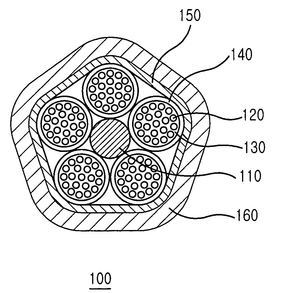
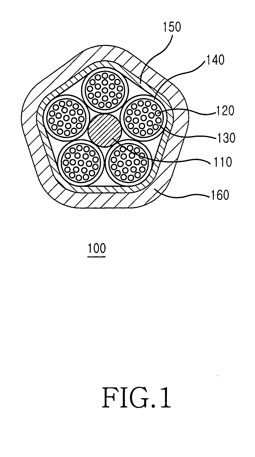
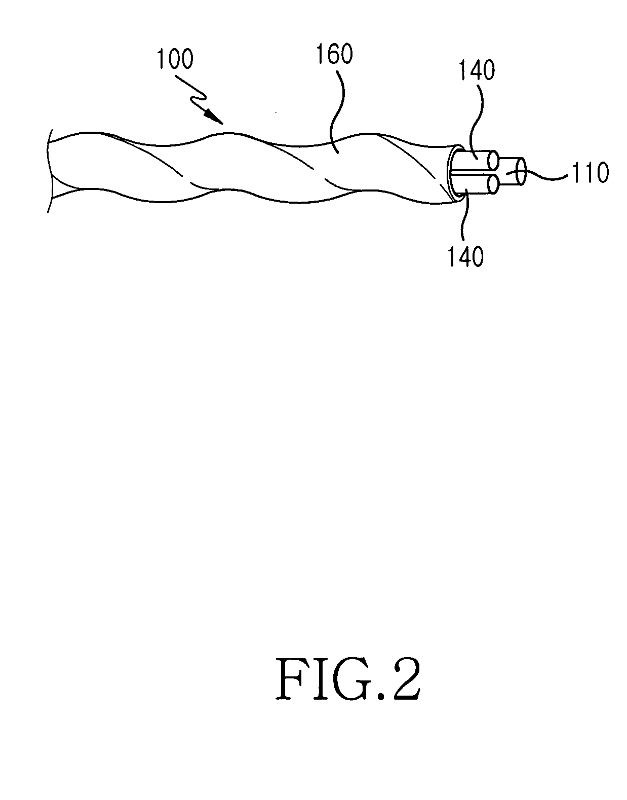
[0018]FIG. 1 is a sectional view showing an optical fiber cable according to a first embodiment of the present invention. As shown, an optical fiber cable 100 includes a center tensile member 110, a plurality of optical fibers 120, a plurality of loose tubes 140, a binder 150, and a sheath 160.
[0019] The center tensile member 110 provides tension-resistant force to the optical fiber cable 100, and is located substantially at a center of the optical fiber cable 100. The center tensile member 110 may be made of FRP (Fiberglass Reinforced Plastic).
[0020] The plurality of loose tubes 140 are aligned in such a manner that they surround the center tensile member 110, and have at least one optical fiber 120 therein. The loose tubes 140 can be located at a peripheral of the center tensile member 110 as a linear pattern, a helical pattern, or an S-Z pattern. Such alignment patterns have been already known in the art. For example, the S-Z pattern is particularly described in U.S. Pat. No. 4,828,352, which is issued to Heinrich A. Kraft, and entitled “S-Z STRANDED OPTICAL CABLE”.
[0021] Also, a hollow space 130 of the loose tubes 140 can be filled with jelly compound, and the jelly compound protects the optic fibers 220 from external shock and absorbs moisture penetrated into an interior of the optical fiber 120. For example, each of the loose tubes 140 has a diameter in a range of 1.6 mm to 2.0 mm. In a case in which the loose tubes 140 are aligned in the helical pattern or the S-Z pattern, a total pitch thereof is less than 150 mm. In this case, the sheath 160 has a thickness identical to or less than 1.0 mm.
[0022] The binder 150 surrounds the loose tubes 140 to maintain the alignment of the loose tubes 140. The binder 150 surrounds the loose tubes 140 in a helical pattern, and has a total pitch identical to or less than 150 mm. The binder 150 may include, for example, a tape, a polyester yarn, or an aramid yarn. When using the aramid yarn, a waterproof aramid yarn is used in order to achieve a waterproof function, or a rigid aramid yarn in order to enhance strength, or combination thereof will be used in order to ensure the waterproof function and strength improvement.
[0023] The sheath 160 is located at an outermost part of the optical fiber cable 100. The sheath 160 may include high-polymer compounds such as PVC, PE, hytrel, nylon and polypropylene. The sheath 160 may be manufactured by an extrusion process. In addition, the sheath 160 can include a rip cord (not shown) adjacent to an inner wall thereof to easily peel off the sheath 160. For example, the sheath 160 may have a thickness identical to or less than 1.0 mm.
[0024] The optical fiber cable 100 may have a polygonal sectional shape, in which edges thereof are smoothly formed. For example, FIG. 1 shows an embodiment using a pentagonal sectional shape. It should be understood that other polygonal sectional shapes may be used, e.g., triangular, rectangular and octagonal. FIG. 2 shows a schematic perspective view of the optical fiber cable 100 in a case in which the loose tubes 140 are aligned in the helical form. The optical fiber cable 100 for the air-blown installation requires a relatively small tensile force as compared with the optical fiber cable for the tension installation method. This allows the optical fiber cable 100 to be suitable for air blown installation even if it has no auxiliary tensile member.
[0025] In this embodiment, because the section shape of the optical fiber cable 100 forms a pentagonal shape having smooth edges, the frictional coefficient of the optical fiber cable 100 with respect to a cable duct is small, and therefore, the optical fiber cable 100 is easily moved when air is applied to the optical fiber cable 100.
[0026] Table 1 shows a test result representing frictional coefficient of optical fiber cables with respect to cable duct according to sectional shapes of the cable.
[0027] Two kinds of cable ducts manufactured by different companies are used for the test. The optical fiber cables have the same weight and the same circular sectional shapes. TABLE 1 Sectional shape of Frictional coefficient in Frictional coefficient cable duct A in duct B Circular shape 0.146 0.096 Pentagonal shape 0.126 0.078 having smooth edges
[0028] As described above, as the optical fiber cable for an air-blown installation according to one embodiment of the present invention has a pentagonal sectional shape having smooth edges, frictional coefficient between the optical fiber cable for an air-blown installation and the duct is reduced. This allows the optical fiber cable to be easily moved when air is applied thereto.
[0029] Also, the optical fiber cable for the air-blown installation according to other embodiments of the present invention may have a smaller size and/or a lighter weight and/or may have a reduced number of internal components as compared to conventional optical fiber cables.
[0030] While the invention has been shown and described with reference to certain embodiments thereof, it will be understood by those skilled in the art that various changes in form and details may be made therein without departing from the spirit and scope of the invention as defined by the appended claims.

PUM

no PUM

Description & Claims & Application Information

We can also present the details of the Description, Claims and Application information to help users get a comprehensive understanding of the technical details of the patent, such as background art, summary of invention, brief description of drawings, description of embodiments, and other original content. On the other hand, users can also determine the specific scope of protection of the technology through the list of claims; as well as understand the changes in the life cycle of the technology with the presentation of the patent timeline. Login to view more.

Similar technology patents

Classification and recommendation of technical efficacy words

  • Reduce number of component
  • Light weight

Toner cartridge

Owner:KYOCERA DOCUMENT SOLUTIONS INC

Protection of anodes for electrochemical cells

InactiveUS20100104948A1Light weightAlkaline accumulatorsElectrode manufacturing processesSulfur containingElectrochemical cell
Owner:SION POWER CORP

Housing for an Implantable Medical Device

ActiveUS20090171420A1Light weightIncrease manufacturing efficiencyInternal electrodesExternal electrodesMagnetic fluxElectrical and Electronics engineering
Owner:CYBERONICS INC
Why Eureka
Try Eureka