Swash plate type hydraulic pump or motor

a hydraulic pump and motor technology, applied in the direction of reciprocating piston engines, positive displacement liquid engines, positive displacement engines, etc., can solve the problems of complex hydraulic fluid passage and valve mechanism that switches the flow of hydraulic fluid in order to supply and discharge hydraulic fluid to and from the pistons disposed on both sides of the cylinder block, and the supply and discharge efficiency of hydraulic fluid is worsened

Inactive Publication Date: 2005-05-05
KYB CORP
View PDF7 Cites 23 Cited by
  • Summary
  • Abstract
  • Description
  • Claims
  • Application Information

AI Technical Summary

Benefits of technology

[0009] It is an object of this invention to provide a swash plate hydraulic pump or motor in which a

Problems solved by technology

However, a hydraulic fluid passage and a valve mechanism that switches flow of the hydraulic fluid in order to supply and discharge the hydraulic fluid to and from the pistons dispo

Method used


Image

  • Swash plate type hydraulic pump or motor
  • Swash plate type hydraulic pump or motor
  • Swash plate type hydraulic pump or motor

Examples


Embodiment Construction

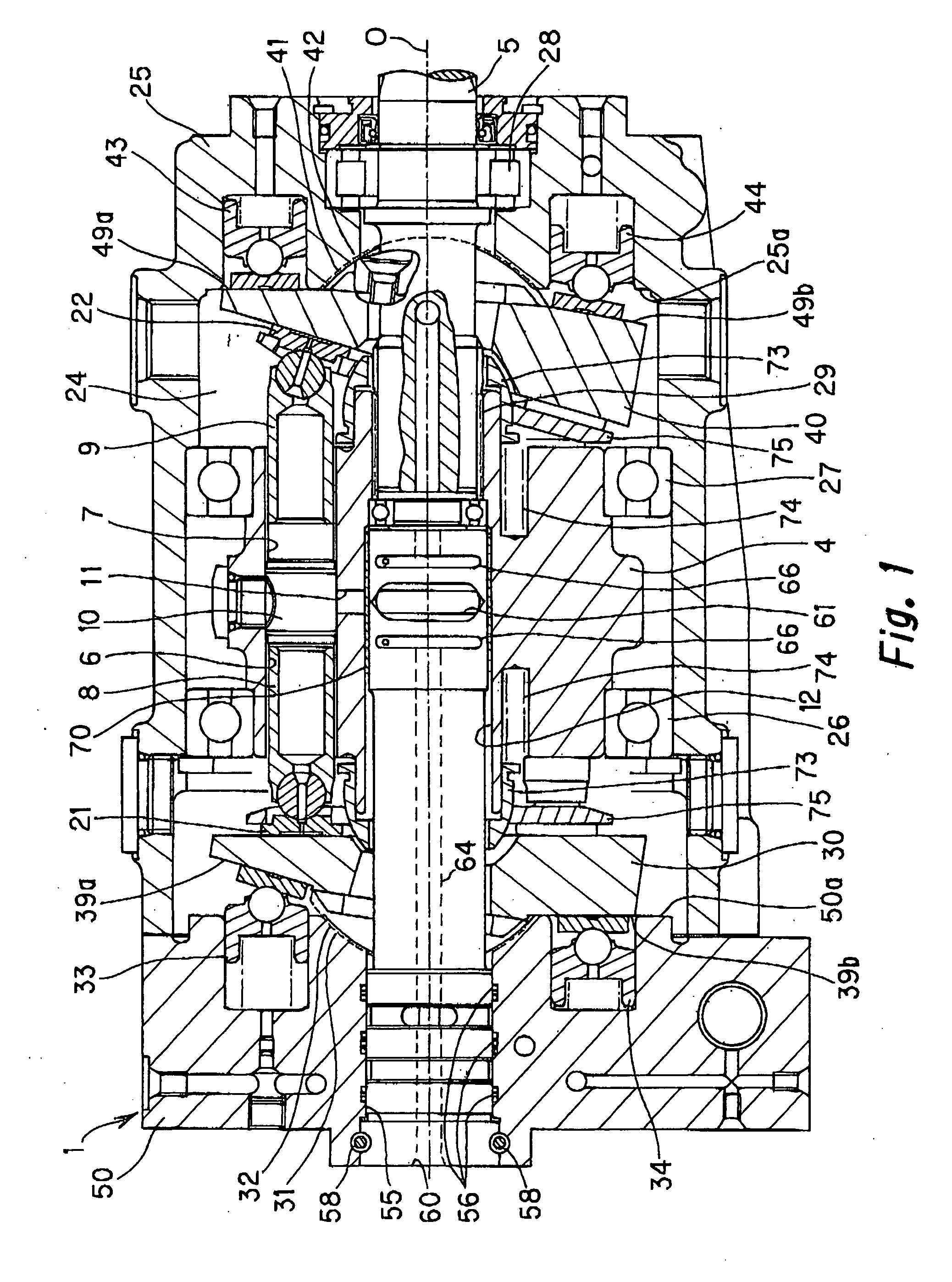
[0016] Embodiments of this invention applied to a hydraulic motor of an HST installed in an industrial vehicle or the like will be explained below based on the appended drawings.

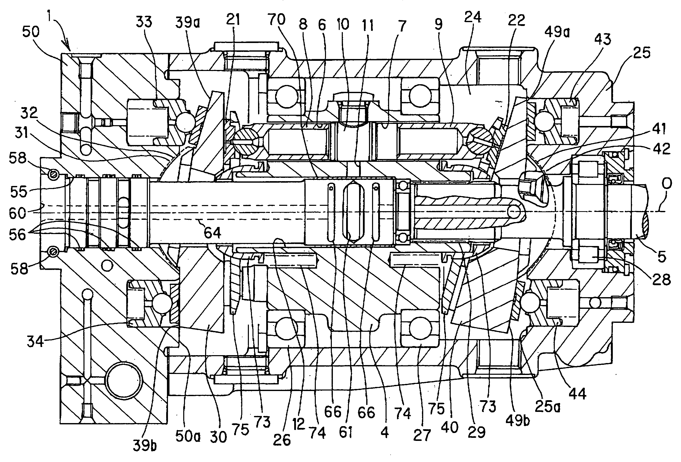
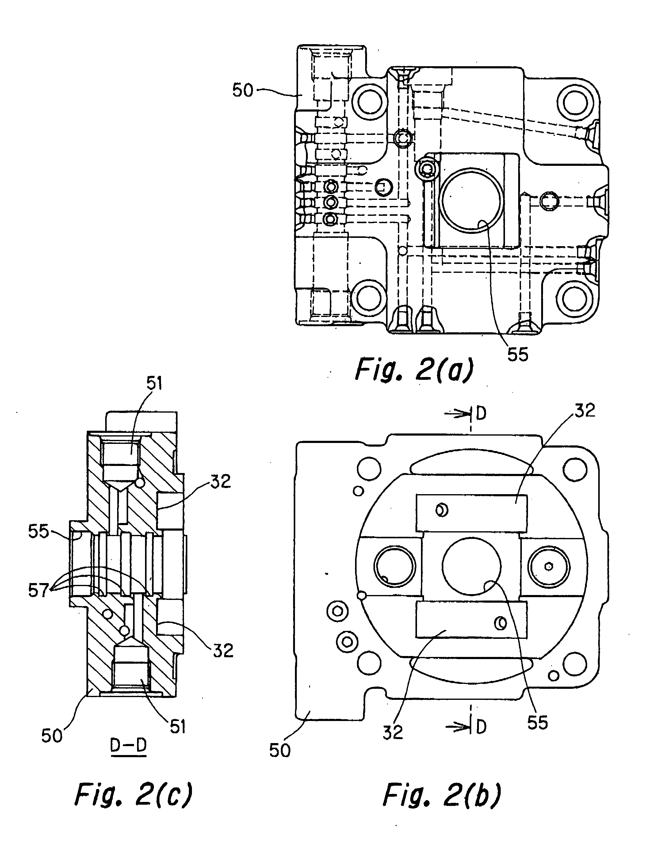
[0017] Referring to FIG. 1, a hydraulic motor 1 comprises a cylindrical case 25 and a port block 50 that is connected to the case 25. The hydraulic motor 1 is a swash plate type hydraulic pump or motor. A housing chamber 24 is provided in inner portions of the cylindrical case 25 and the port block 50. A cylinder block 4, a first swash plate 30, and a second swash plate 40 are housed in the housing chamber 24.

[0018] The cylinder block 4 is joined on an axis of a shaft 5 that is disposed in a center portion of the case 25, and the shaft 5 and the cylinder block 4 rotate integrally.

[0019] Consequently, a distal end portion of the shaft 5 is connected to an inner circumference of the cylinder block 4, through a spline 29. The shaft 5 is supported by the case 25, through a bearing 28, in an area where it pass...


PUM


Abstract

A swash plate type hydraulic pump or motor has a first swash plate (30) and a second swash plate (40) which cause a first piston (8) and a second piston (9), respectively, to move reciprocally, opposing each other, so as to expand and contract a volume chamber (10) according to rotation of a cylinder block (4). A rod shape valve body (60) is disposed pushed into a through hole (12) of a shaft axis of the cylinder block (4) so as to be free to rotate relative to the cylinder block (4). A pair of supply and discharge ports (61) that open and supply high pressure and low pressure, respectively, are formed in an outer circumferential surface of the valve body (60). A cylinder port (11) is formed connecting the volume chamber (10) and an inner circumferential surface of the through hole of the cylinder block. The cylinder port (11) is arranged in a position opposite to the supply and discharge port (61).

Description

FIELD OF THE INVENTION [0001] This invention relates to a swash plate type hydraulic pump or motor capable of being applied to hydrostatic transmission (hereinafter called HST), which is used in a running gear or the like in agricultural machinery, industrial vehicles, and construction machinery. BACKGROUND OF THE INVENTION [0002] HST is a combination of a hydraulic pump and a hydraulic motor. Consequently, by Changing the tilt angle of a swash plate in the hydraulic pump, and by changing the discharge amount in a range from zero to a maximum discharge amount, the rotational velocity of the hydraulic motor changes. A vehicle can thus continuously change speeds from a stopped state to a maximum forward or reverse speed. [0003] Structures that comprise a single swash plate, a cylinder block, and a plurality of pistons that are housed on only one side of the cylinder block are often used as HST hydraulic pumps or hydraulic motors. [0004] However, the size of the HST hydraulic pump or t...

Claims


Application Information

Patent Timeline
IPC IPC(8): F01B3/00F03C1/06F03C1/24F03C1/26F04B1/20F04B1/22
CPCF01B3/0035F04B1/22F04B1/205
Inventor SHIMIZU, TAKEO
Owner KYB CORP
Why Eureka
Try Eureka