Gripper for catheter shaft

a catheter shaft and gripper technology, applied in the field of medical devices, can solve the problems of difficult or inefficient movement to a holding position

Inactive Publication Date: 2005-05-05
CORDIS CORP
View PDF3 Cites 43 Cited by
  • Summary
  • Abstract
  • Description
  • Claims
  • Application Information

AI Technical Summary

Problems solved by technology

This unscrewing operation must generally be done with two hands; this kind of guidewire gripper effectively provid...

Method used


Image

  • Gripper for catheter shaft
  • Gripper for catheter shaft
  • Gripper for catheter shaft

Examples


Embodiment Construction

[0024] The following description of the preferred embodiments of the present invention is merely illustrative in nature, and as such it does not limit in any way the present invention, its applications, or uses. Numerous modifications may be made by those skilled in the art without departing from the true spirit and scope of the invention.

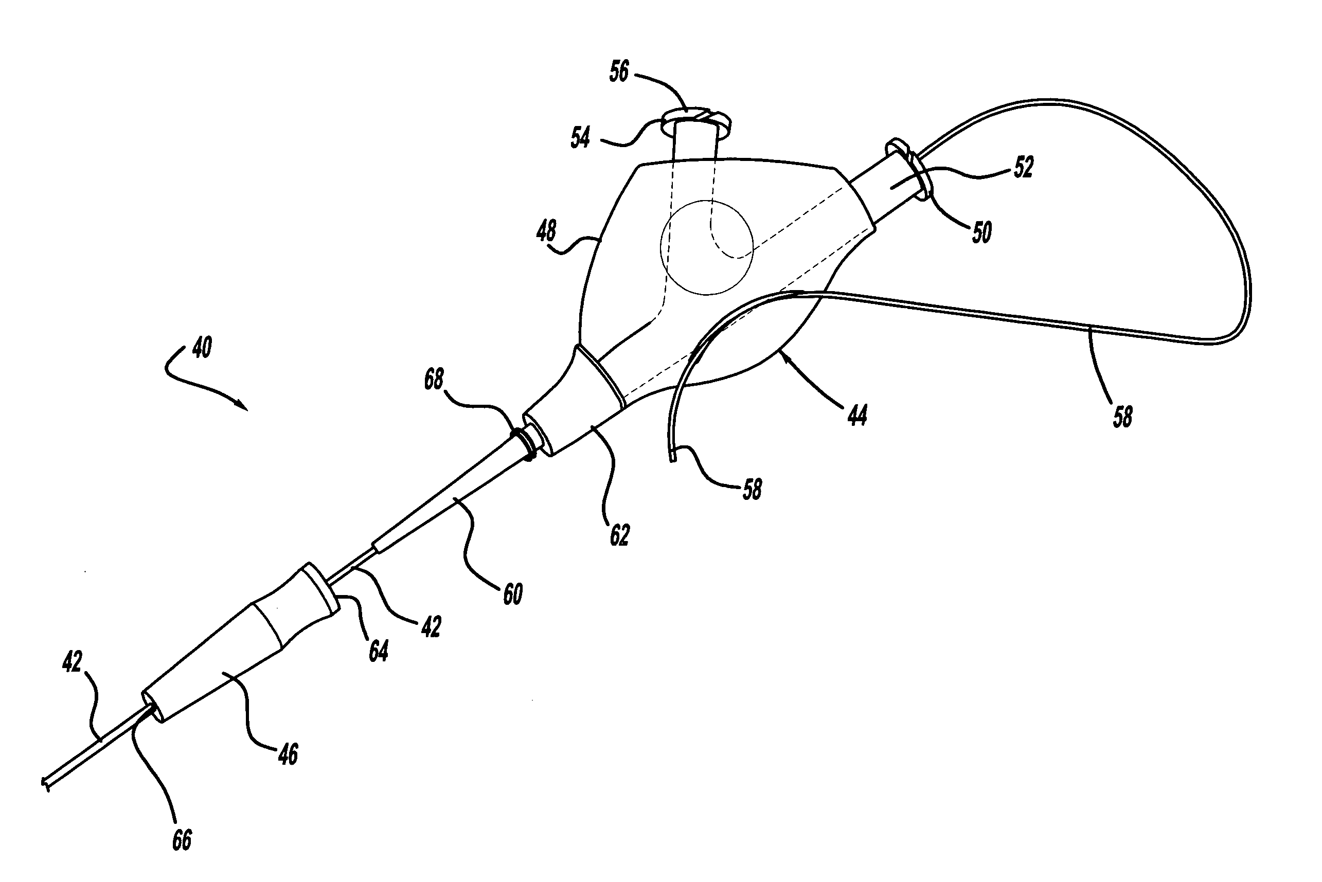
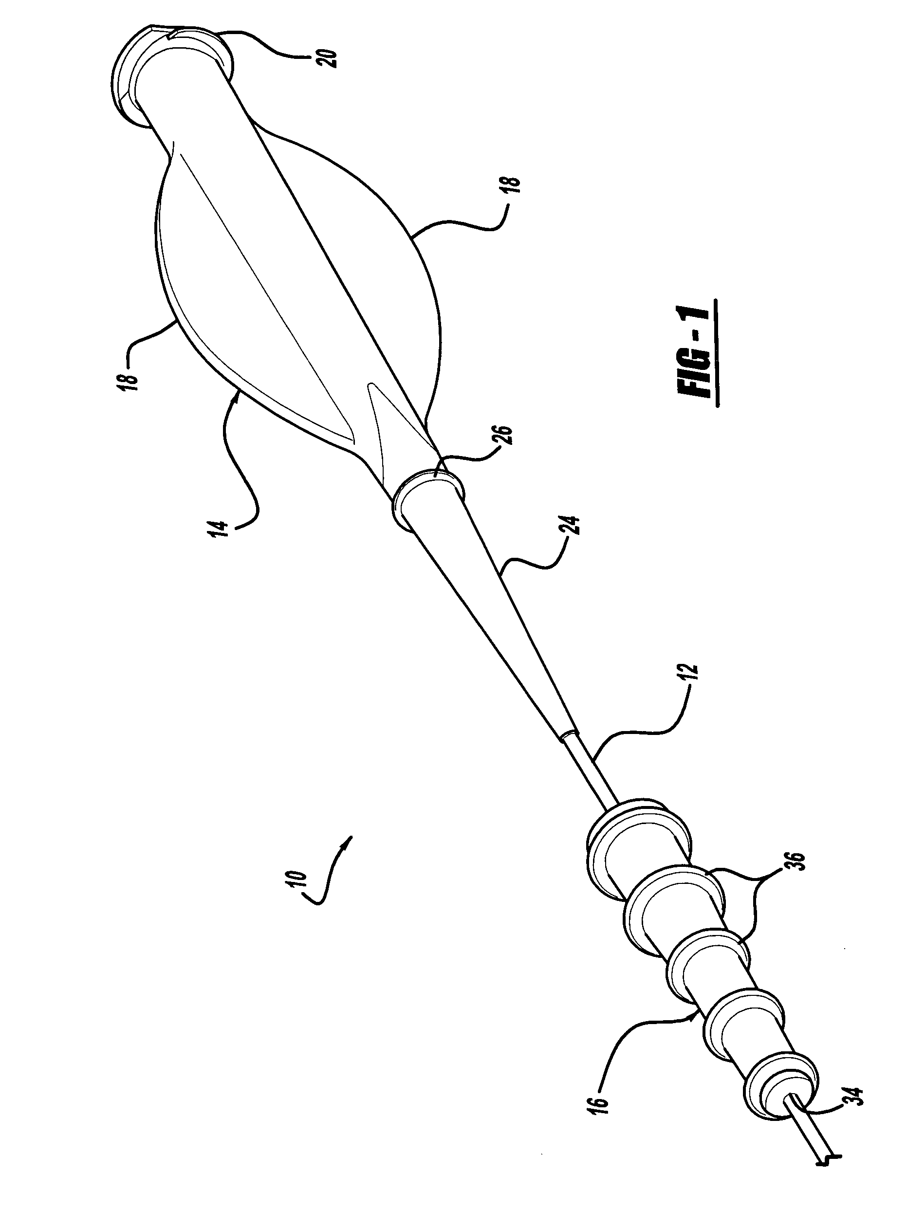
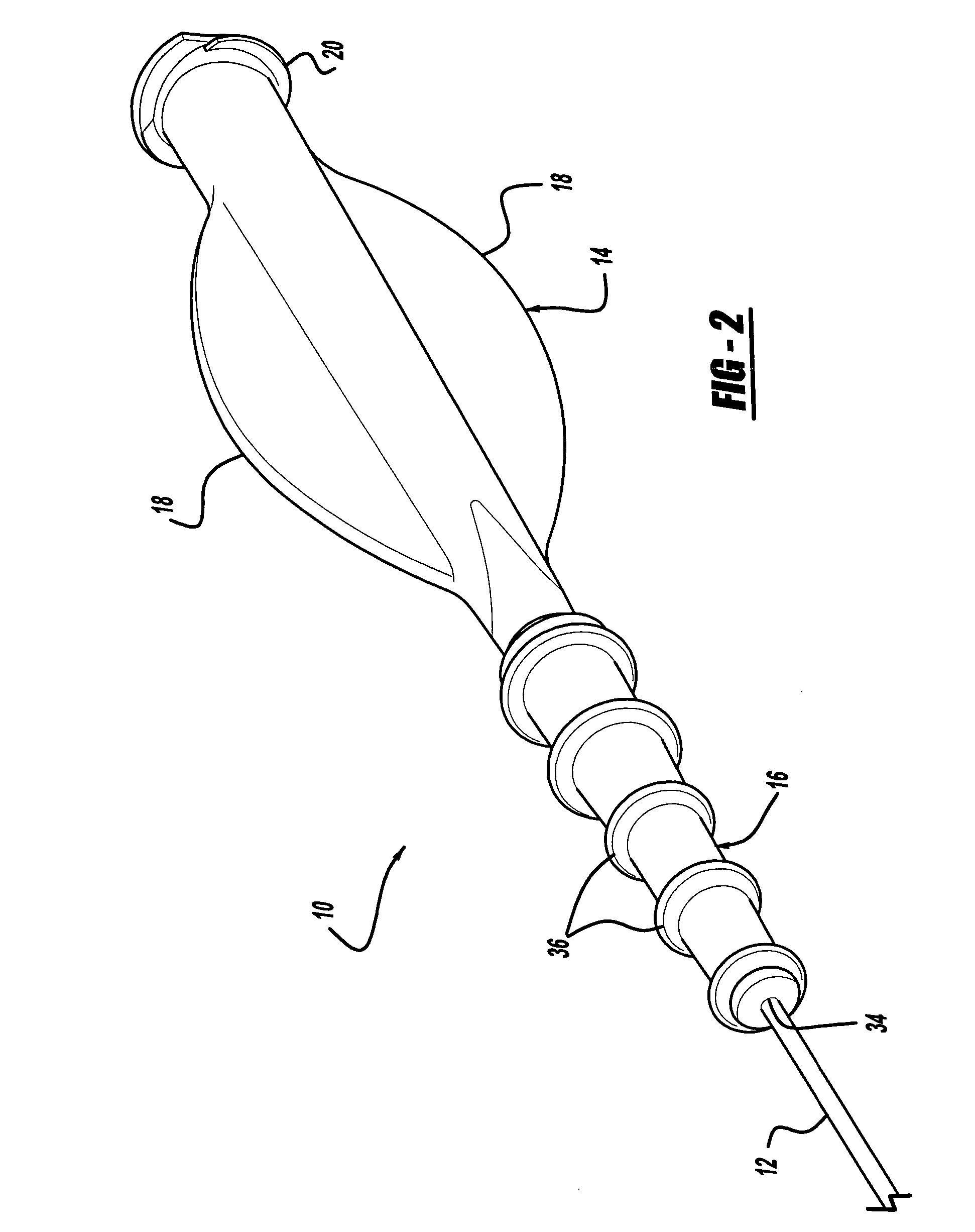
[0025] Referring to the drawings, a gripper and catheter system is shown, with one of the preferred embodiments of the present invention being shown generally at reference numeral 10.

[0026] The catheter system 10 in FIGS. 1 and 2 has a catheter shaft 12, a hub 14 affixed to a proximal end of catheter shaft 12, and a tubular gripper 16 positioned around a portion of the catheter shaft 12. The hub may have some kind of outward extension for providing a physician with a good grip of the proximal end of the shaft, for example the pair of radially extending wings 18 shown in FIGS. 1 and 2. The proximal end of the hub may have a luer-lock fitting 20 an...


PUM


Abstract

A gripper for a catheter shaft is a flexible tube surrounding a portion of the catheter shaft. A physician can move the gripper to a selected position on the catheter shaft, and then squeeze the outer surfaces of the gripper, which resiliently collapses around the catheter shaft. When squeezed, an inner surface of the gripper contacts the catheter shaft and can transmit forces applied by the physician to the outside of the gripper, including twisting of the catheter shaft or longitudinal pushing or pulling. The physician may then release the squeezing pressure, and has the option to move the gripper along the catheter shaft to a different position, and may choose to use the gripper at the new position by squeezing it again.

Description

BACKGROUND AND SUMMARY OF THE INVENTION [0001] 1. Technical Background [0002] The present invention relates generally to medical devices, and more particularly to a gripper for use with a catheter shaft. [0003] 2. Discussion [0004] Catheters are used in a wide variety of therapeutic medical applications. They are often relatively long, on the order of two to five feet in length. They are often relatively thin and flexible, having an outer dimension on the order of several millimeters or less. When a physician wants to manipulate the catheter by grasping a portion of the catheter shaft and moving it, the physician may sometimes desire a better grip on the catheter shaft. This may be particularly true if that portion of the catheter shaft is wet, or has saline or body fluids on it. In addition, the catheter shaft may have any of a variety of coatings, including various lubricious coatings such as a hydrophilic coating. [0005] By way of example, the present invention will be partly des...

Claims


Application Information

Patent Timeline
IPC IPC(8): A61M25/00A61M29/00
CPCA61M25/00A61M25/0113A61M2025/0098
Inventor SLAZAS, ROBERTKENNY, GREGGLEE, WILLIAM
Owner CORDIS CORP
Why Eureka
Try Eureka