

Vehicular pedestrian determining system
a technology for pedestrians and determining systems, applied in the direction of pedestrian/occupant safety arrangements, process and machine control, instruments, etc., can solve the problems of inability to operate protection devices, serious injuries, and inability to protect pedestrians. to be always operated, so as to improve the accuracy of determining
- Summary
- Abstract
- Description
- Claims
- Application Information
AI Technical Summary
Benefits of technology
Problems solved by technology
Method used
Image

Examples
first embodiment
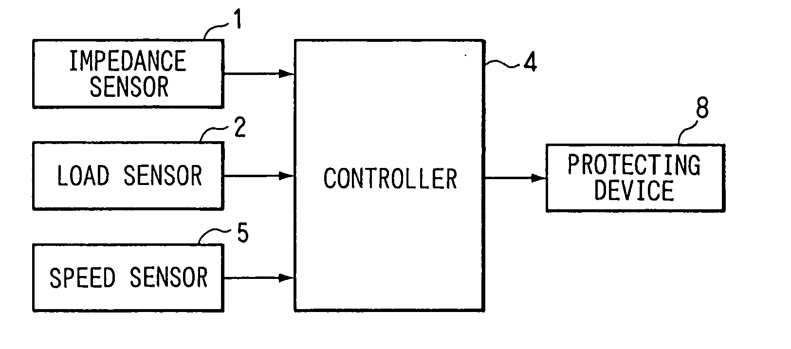
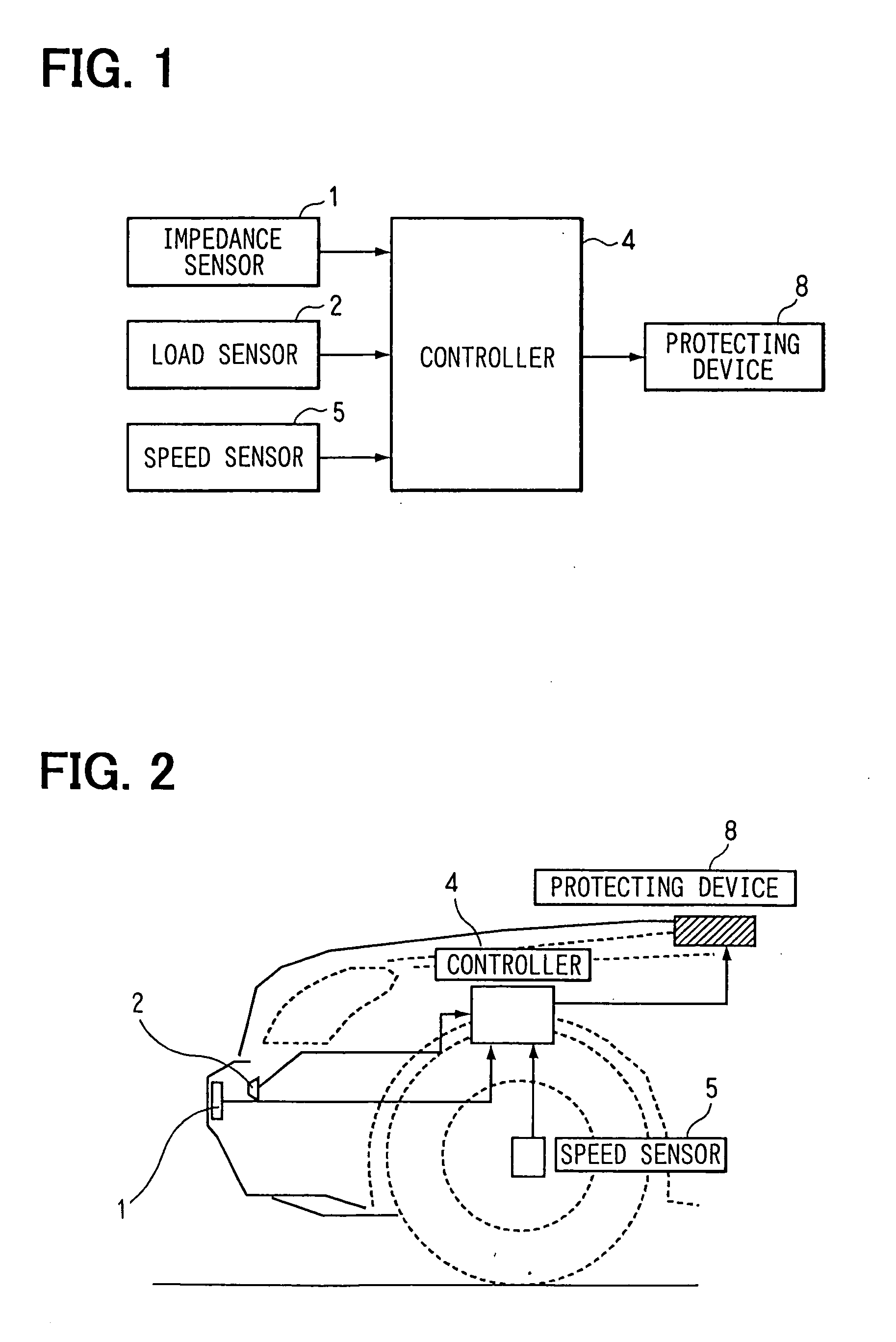
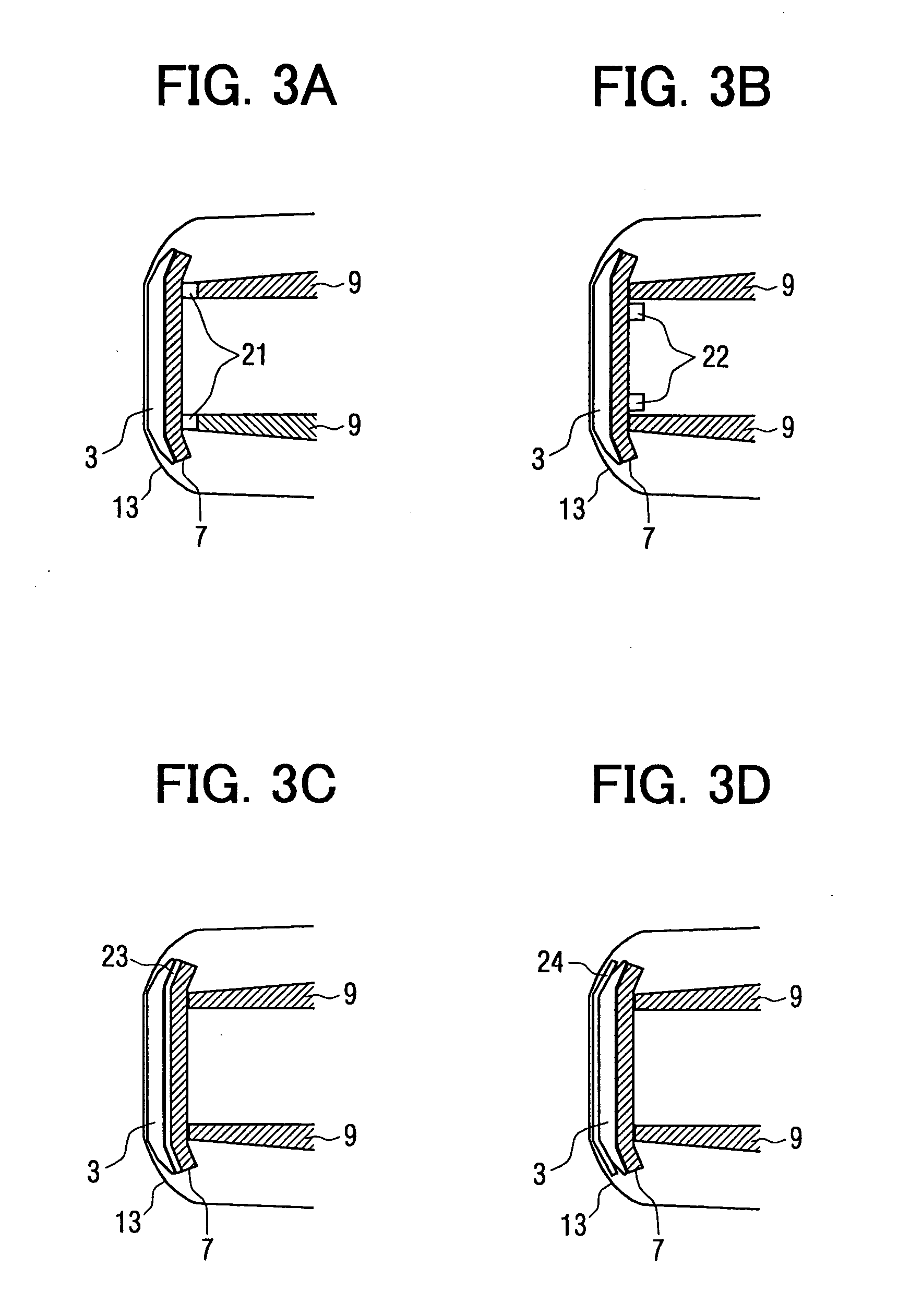
[0029] A structure of a vehicular pedestrian determining system on a vehicle according to a first embodiment of the present invention will be explained with reference to FIGS. 1, 2, 3A to 3D. The vehicle includes an impedance sensor 1, a collision load sensor 2, a bumper cover 13, a bumper absorber 3, a bumper reinforcement 7, a side member 9, a controller 4 for computing and determining, a wheel speed sensor 5 as a vehicle speed sensor, a pedestrian protecting device 8 (pedestrian-protecting airbag), and a vehicle body 6. Here, the bumper cover 13, the bumper absorber 3, and the bumper reinforcement 7 mainly constitute a bumper of the vehicle.
[0030] The impedance sensor 1 will be explained with reference to FIG. 4. The impedance sensor 1 includes a coil L fixed on the bumper absorber 3; an LCR circuit 11 formed of a capacitor C0 parallelly connected with both the coil L and a resistance R1; a resistance R2 serially connected with the LCR circuit 11 for detecting an electric voltag...
second embodiment
[0054] A second embodiment will be explained with reference to FIG. 8. A pedestrian determining process in the second embodiment is modified from that in the first embodiment. A flowchart diagram includes Steps S130 to S148 basically in addition to Steps included in FIG. 6. Here, a threshold value Tth—0 at Step S120 in FIG. 8 corresponds to a threshold value Tth at Step S120 in FIG. 6.
[0055] At Step S116, when the read collision load F(t) is determined to be the given threshold value Fth—0 or more, an impedance signal L(t) at this moment is read and memorized as a collision-moment impedance value L0 at Step S130. A second timer T1 is then started at Step S132.
[0056] Next, a collision load F(t) is read at Step S134. It is then determined whether the collision load F(t) is a given threshold value Fth—1 or more at Step S136. When the collision load F(t) is determined to be the given threshold value Fth—1 or more, an impedance signal L(t) is read as a value L1 at Step S138. A change r...
third embodiment
[0065] A third embodiment will be explained with reference to FIG. 10. This embodiment is a modification of the first embodiment. A flowchart in FIG. 10 includes Steps S150 to S180 in addition to the flowchart in FIG. 6. However, when the count time of the timer T0 exceeds the threshold value Tth—0 at Step S120, no collision occurrence is determined, which returns the process to the main routine.
[0066] When the impedance signal L(t) is determined to be the lower threshold value Lth—1 or less at Step S106, a collision load F(t) is read at Step S160. It is determined whether the read collision load F(t) is the threshold value Fth—0 or more at Step S162. When the read collision load F(t) is determined to be less than the threshold value Fth—0, the process returns to Step S100. When the read collision load F(t) is determined to be the threshold value Fth—0 or more, a wheel speed V as the vehicle speed is read at Step S164. It is determined whether the wheel speed V is the given thresho...
PUM
 Abstract
Description
Claims
Application Information