Methods for designing a chamber to reduce noise in a duct

a technology of duct noise reduction and design method, which is applied in the direction of noise figure or signal-to-noise ratio measurement, instruments, digital computer details, etc., can solve the problems of ineffective low frequency range of existing sound absorption techniques, increased concern about dust accumulation in the pores of porous materials, and often over-looked ranges. to achieve the effect of reducing nois

Inactive Publication Date: 2005-05-05
THE HONG KONG POLYTECHNIC UNIV
View PDF0 Cites 13 Cited by
  • Summary
  • Abstract
  • Description
  • Claims
  • Application Information

AI Technical Summary

Benefits of technology

[0024] It is another aspect of this invention to provided a chamber attaching to a duct having a height h for reducing noise in said duct, including a peripheral chamber height hc and membrane length L, and a

Problems solved by technology

Firstly, existing sound absorption techniques may be ineffective in the low frequency range, such as that below 200 Hz.
This range is also often over-looked due to its low A-weighting.
Secondly, there has been increasing concern about the deposition and accumulation of dusts in the pores of the porous material.
A periodical cleaning

Method used


Image

  • Methods for designing a chamber to reduce noise in a duct
  • Methods for designing a chamber to reduce noise in a duct
  • Methods for designing a chamber to reduce noise in a duct

Examples


Embodiment Construction

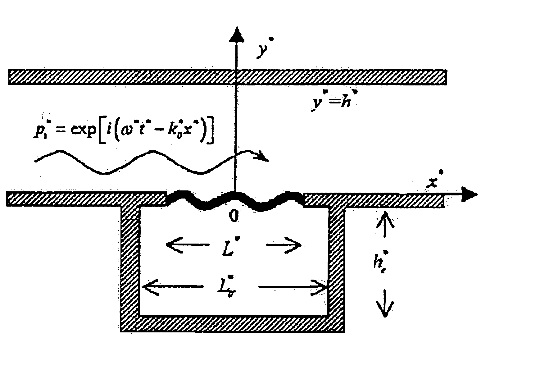
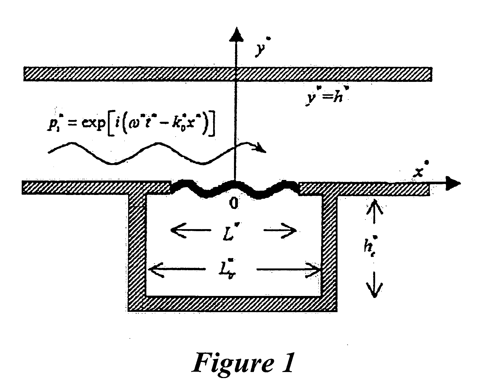
[0035] This invention is now described by way of example with reference to the figures in the following paragraphs. List 1 contains a list of symbols used in this specification so that such may be easily referred to.

[0036] Objects, features, and aspects of the present invention are disclosed in or are obvious from the following description. It is to be understood by one of ordinary skill in the art that the present discussion is a description of exemplary embodiments only, and is not intended as limiting the broader aspects of the present invention, which broader aspects are embodied in the exemplary constructions.

[0037] In the field of architectural acoustics, analytical efforts have been made to predict the acoustic performance of such panels. For example, Kang and Fuchs (1999) successfully treated the problem of microperforated membrane as a parallel connection of the (impervious) membrane and apertures. This is a locally reactive model which nevertheless reveals most of the es...


PUM


Abstract

Low-frequency duct noise is relatively difficult to deli with by passive methods such as porous duct lining. Reactive methods like expansion chamber are rather bulky, while compact resonators are too narrow-banded. This invention shows that a suitably stretched thin membrane backed by a slender cavity can achieve a satisfactory performance from low to medium frequencies over an octave band.

Description

FIELD OF THE INVENTION [0001] This invention relates to method for determining at least one parameter for the design of a least one chamber including a tensioned membrane to reduce noise in a duct. BACKGROUND OF THE INVENTION [0002] Porous media have been the backbone of almost all dissipative noise abatement techniques. This may be a mature and reliable technique which works for a very broad frequency band. But there may be two drawbacks. [0003] Firstly, existing sound absorption techniques may be ineffective in the low frequency range, such as that below 200 Hz. This range is also often over-looked due to its low A-weighting. Nevertheless, the actual power of noise radiation from, say, a fan, is often highest in this frequency range. [0004] Secondly, there has been increasing concern about the deposition and accumulation of dusts in the pores of the porous material. A periodical cleaning of the lining would be rather costly and indeed tedious. In fact, there are already public con...

Claims


Application Information

Patent Timeline
IPC IPC(8): G10K11/172H04B15/00
CPCH04B15/00G10K11/172
Inventor HUANG, LIXICHOY, YAT-SZE
Owner THE HONG KONG POLYTECHNIC UNIV
Why Eureka
Try Eureka