

Network branch placement tool
- Summary
- Abstract
- Description
- Claims
- Application Information
AI Technical Summary
Benefits of technology
Problems solved by technology
Method used
Image

Examples
Embodiment Construction
[0033] Referring now in detail to the drawings wherein like reference numerals identify similar structural features of the several embodiments of the subject invention. As used here, “service receiver” is understood to include recipients of products, and “services” is understood to include products; that is, a “service receiver” may be a purchaser of products offered by the service provider, and the “services” rendered by the service provider may be products sold by the service provider.
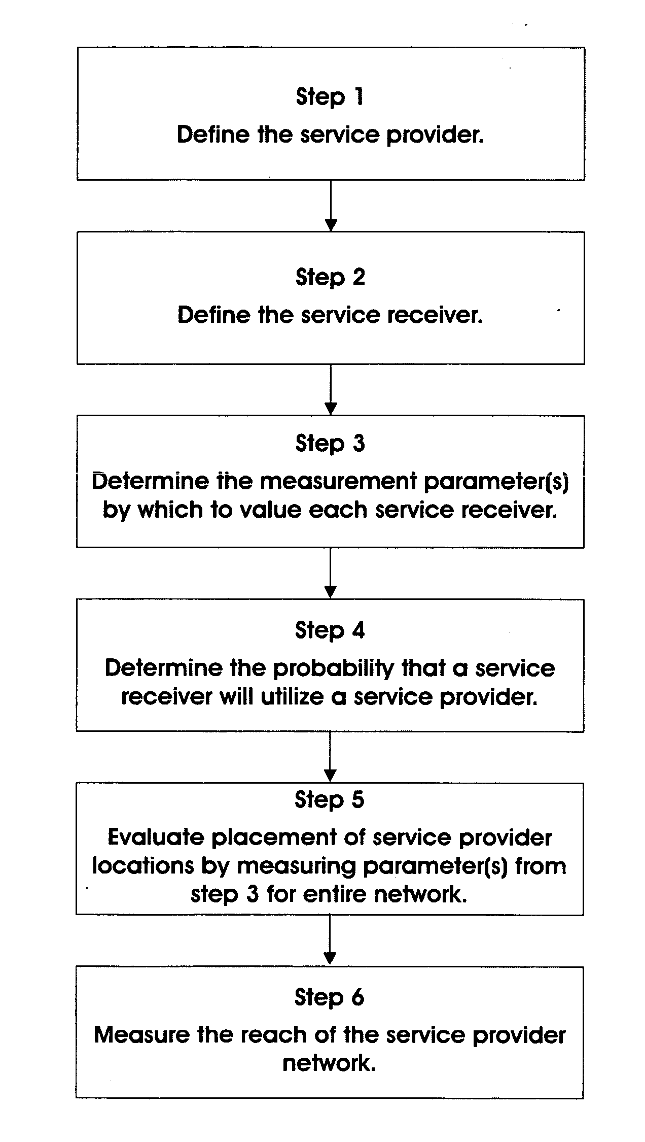
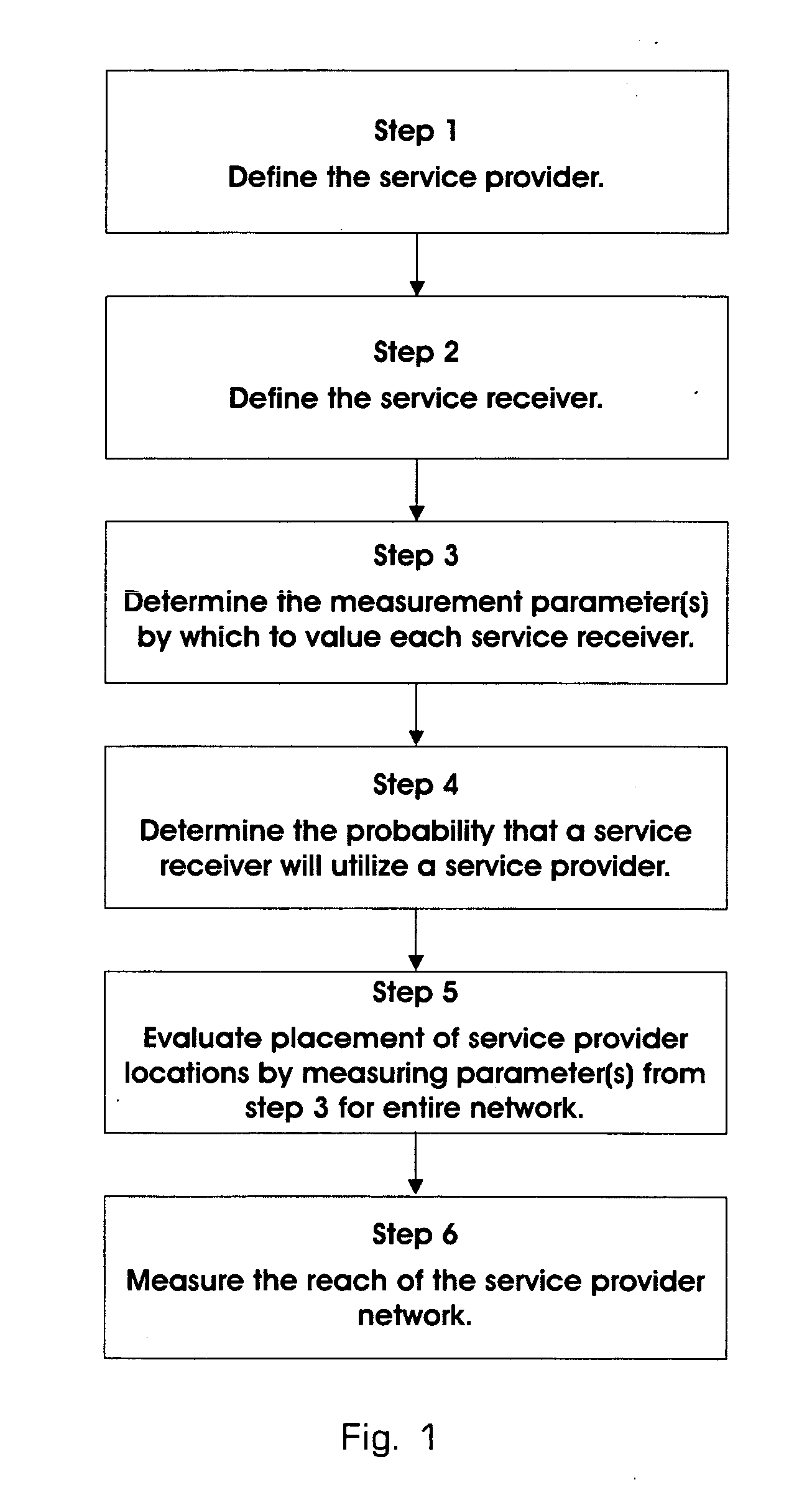
[0034]FIG. 1 is a flow chart enumerating the steps of a preferred embodiment of the present invention. The several steps of FIG. 1 and other figures herein may proceed in the order illustrated; however, other ordering of the steps may also be utilized provided that input information required for any step is available prior to the commencement of that step. Thus, for example, steps 1 and 2 which follow may be interchanged chronologically without altering the outcome of the process.
[0035] The process...
PUM
 Abstract
Description
Claims
Application Information