Heat treated devolatilizer nozzle

a devolatilizer and nozzle technology, applied in heat treatment apparatus, furnaces, separation processes, etc., can solve the problems of manufacturing reliability, lower ductility and greater hardness, and more difficult perforation of metal and rolling it into the hoop or circular

Inactive Publication Date: 2005-05-12
FINA TECH
View PDF6 Cites 16 Cited by
  • Summary
  • Abstract
  • Description
  • Claims
  • Application Information

AI Technical Summary

Benefits of technology

[0009] In an embodiment, a method is provided for perforating a steel plate, forming a devolatilizer nozzle from the steel plate, and heat treating the devolatilizer nozzle. In another embodiment, the devolatilizer nozzle has a yield strength of at least about 110 ksi. In another embodiment, the devolatilizer possesses a tensile strength of at least about 140 ksi. In another embodiment, the perforations in the steel plate are holes...

Problems solved by technology

Higher strength steels may be more resistant to higher pressures, but generally also possess lower ductility and greater hardness, which present manufacturing and reliability issues when producing devolatilizer nozzles.
The lower duct...

Method used


Image

  • Heat treated devolatilizer nozzle
  • Heat treated devolatilizer nozzle
  • Heat treated devolatilizer nozzle

Examples


Embodiment Construction

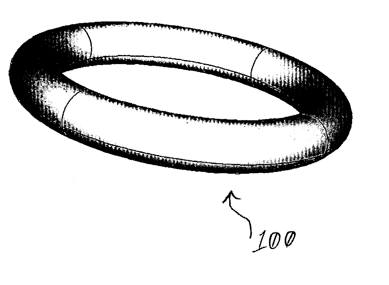
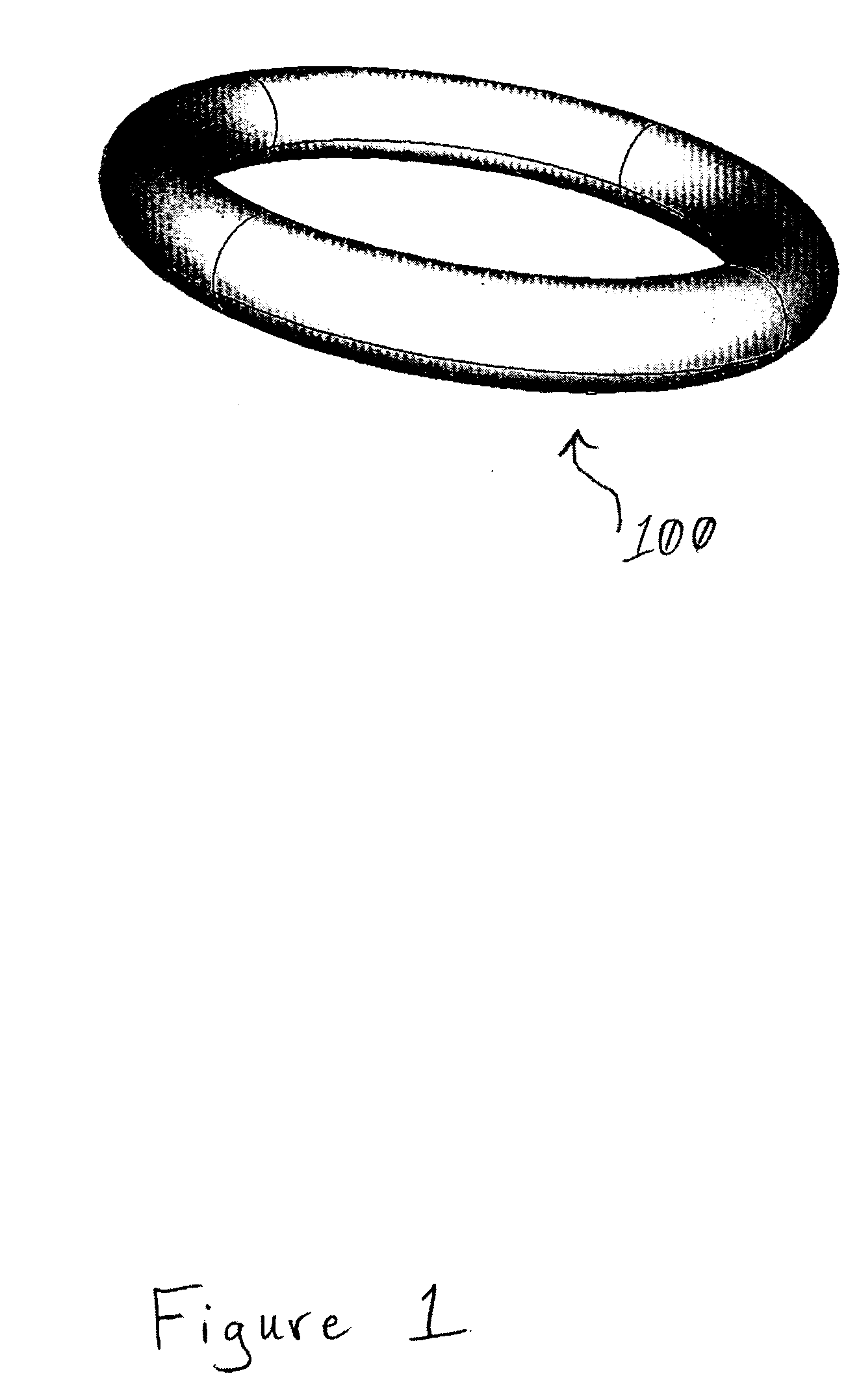
[0018] Devolatilizer nozzles and methods of making same are provided. FIG. 1 illustrates an embodiment of the shape of a devolatilizer nozzle 100 as provided herein. The nozzle 100 is shown without perforations / holes. The nozzle may take any shape that permits polymer to flow through perforations in order to effect devolatilization. Accordingly, the hoop- or donut-shape of the embodiment in FIG. 1 is hollow such that molten polymer may be pumped into the hollow interior. The pressure of pumping the polymer into the hollow interior of the nozzle forces the polymer through perforations (not shown) in the surface of the nozzle, thereby provoking devolatilization.

[0019] In an embodiment of the devolatilizer nozzle and method of making same provided herein, a steel plate is perforated, formed into a devolatilizer nozzle, and heat treated. The heat treatment or tempering results in a stronger finished nozzle capable of withstanding the greater operating pressures associated with smaller ...


PUM

PropertyMeasurementUnit
Thicknessaaaaaaaaaa
Thicknessaaaaaaaaaa
Thicknessaaaaaaaaaa

Abstract

A method is provided for perforating a steel plate, forming a devolatilizer nozzle from the steel plate, and heat treating the devolatilizer nozzle. The devolatilizer nozzle may have a yield strength of at least about 110 ksi, and a tensile strength of at least about 140 ksi. The perforations in the steel plate are holes in the nozzle and may be no more than about 0.05 inches in diameter. The thickness of the steel plate may be from about 0 to about 0.75 inches. The nozzle may include at least about 500,000 perforations where the center-to-center hole distance may be at least about 0.08 inches. The capacity of the devolatilizer nozzle may be from about 0 to about 75,000 pounds per hour.

Description

CROSS-REFERENCE TO RELATED APPLICATIONS [0001] None. STATEMENT REGARDING FEDERALLY SPONSORED RESEARCH OR DEVELOPMENT [0002] Not applicable. REFERENCE TO A MICROFICHE APPENDIX [0003] Not applicable. FIELD OF THE INVENTION [0004] This invention relates generally to devolatilizer nozzles, and, more particularly, to a method of forming a heat treated devolatilizer nozzle capable of improving devolatilization while also maintaining or increasing production capacities. BACKGROUND OF THE INVENTION [0005] Reduction of contaminants, such as monomers and volatiles, in polymer resins is desirable. One method of reducing the volatile content of (i.e., devolatilizing) such polymers involves increasing the exposed surface area of the resin and accordingly promoting the release of volatiles. An apparatus commonly employed in this operation is known as a devolatilizer nozzle. Examples of devolatilizer nozzles may be found in U.S. Pat. Nos. 5,540,813, 4,294,652, 4,934,433, 5,118,388 and 5,874,525, w...

Claims


Application Information

Patent Timeline
IPC IPC(8): B01D3/06B01D19/00
CPCB01D3/06B01D19/0036C21D6/004Y10T29/49995Y10T29/49433Y10T29/49996Y10T29/49432C21D9/46B01D3/00B01D19/00
Inventor CORLETO, CARLOS R.SOSA, JOSE M.
Owner FINA TECH
Why Eureka
Try Eureka