Film forming apparatus

a technology of film forming apparatus and film, which is applied in the direction of coating, molten spray coating, chemical vapor deposition coating, etc., can solve the problems of inability to contribute to film formation, inability to control the thickness of the structure formed on the substrate, and unstable density of raw material powder (aerosol density) contained in the aerosol, etc., to achieve the effect of accurately controlling the thickness of the structure being formed

Inactive Publication Date: 2005-05-12
FUJIFILM HLDG CORP +1
View PDF9 Cites 11 Cited by
  • Summary
  • Abstract
  • Description
  • Claims
  • Application Information

AI Technical Summary

Benefits of technology

[0009] The present invention has been achieved in view of the above-described problems. An object of the present invention is, in a film forming apparatus according to the aerosol deposition method, to control the thickness of a structure to be formed accurately.
[0011] According to the present invention, since the amount of primary particles that have contributed to the film formation can be obtained by using the detecting means, the film forming speed can be directly estimated. Therefore, the thickness of the structure being formed can be controlled accurately.

Problems solved by technology

However, in such an apparatus for fabricating a ceramic structure (film forming apparatus), there occurs a problem that the thickness of the structure formed on the substrate cannot be controlled accurately.
This is because, although the thickness of the structure is controlled by adjusting the relative speed between the substrate and the nozzle in the film forming apparatus according to the AD method, actually the density of the raw material powder (aerosol density) contained in the aerosol is unstable.
However, such agglomerated particles cannot contribute to the film formation because kinetic energy of the agglomerated particles is consumed for crushing themselves.
Here, the ratio cannot be controlled.
Therefore, according to the method of controlling the respective parts of the film forming apparatus on the basis of the consumed amount of raw material powder, the thickness of the structure cannot be controlled accurately, either.

Method used


Image

  • Film forming apparatus
  • Film forming apparatus
  • Film forming apparatus

Examples


first embodiment

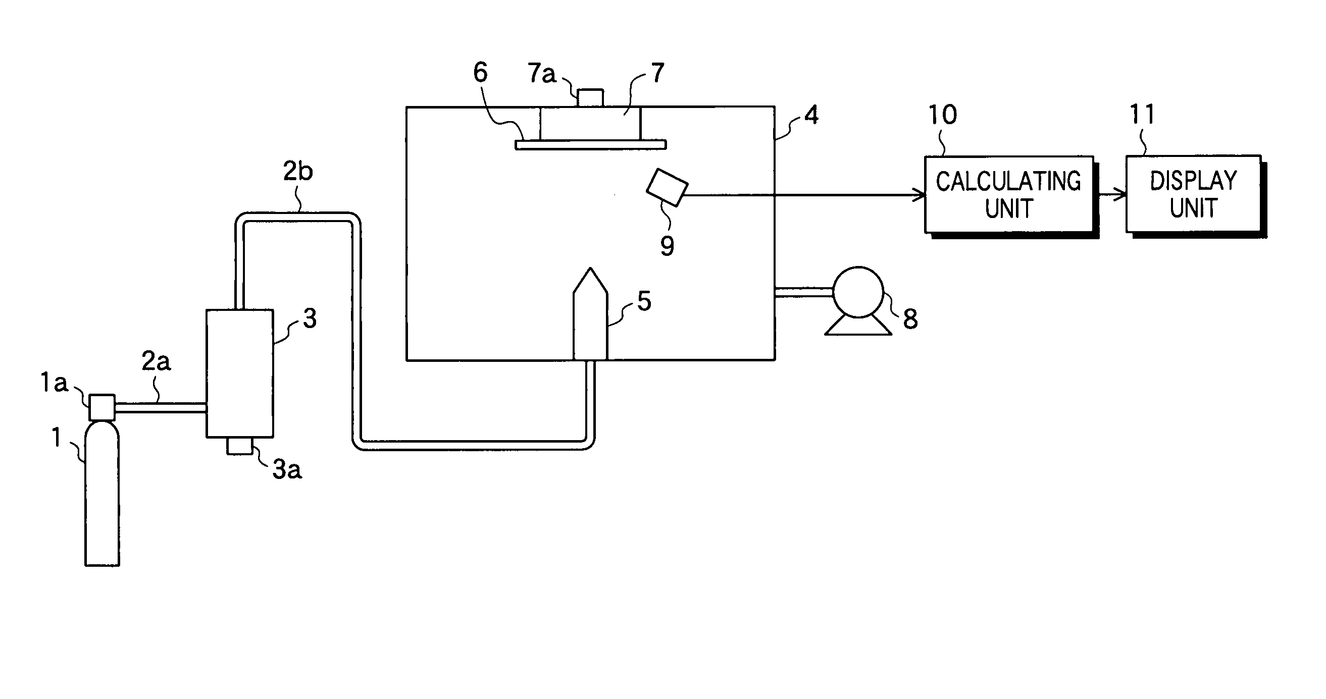
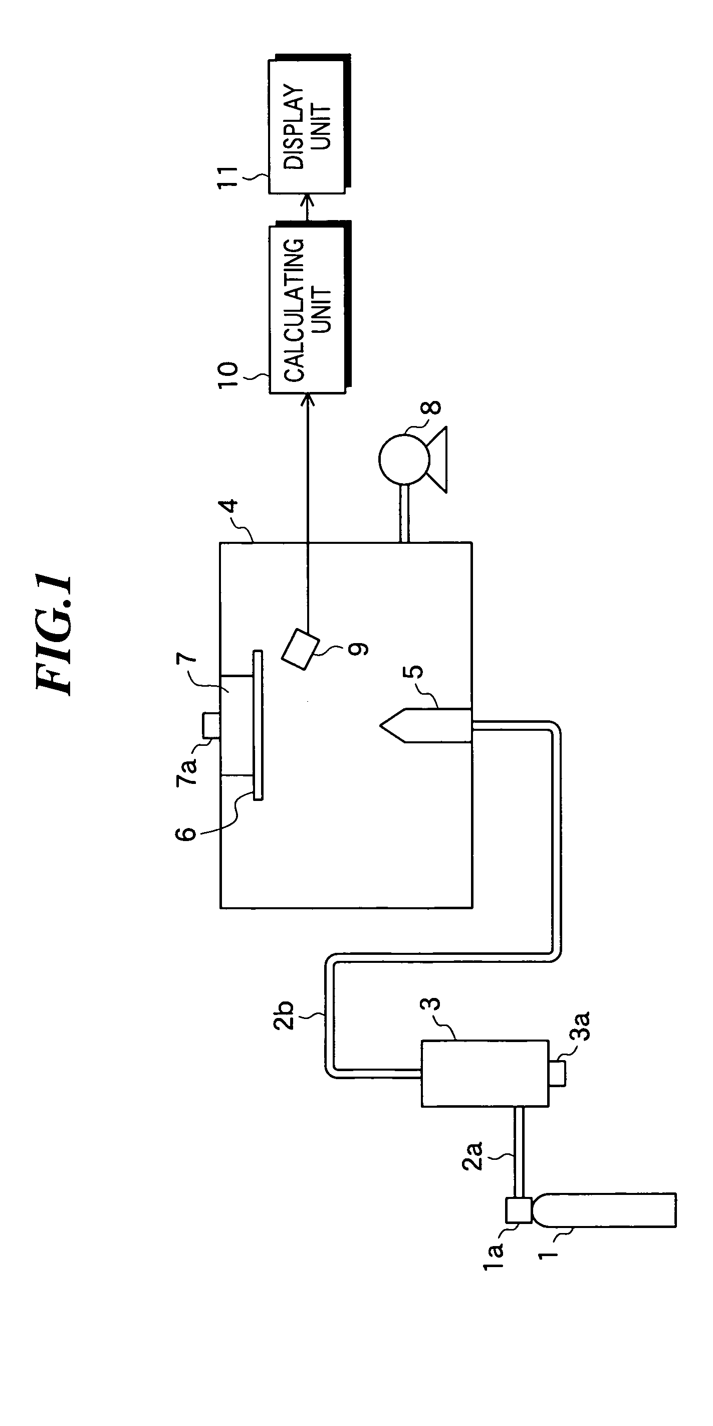
[0016]FIG. 1 is a schematic diagram showing a film forming apparatus according to the present invention. The film forming apparatus includes a compressed gas cylinder 1, carrier pipes 2a and 2b, an aerosol generating part 3, a film forming chamber 4 in which film formation is performed, a nozzle 5 disposed in the film forming chamber 4, a substrate holder 7, an exhaust pump 8, a sensor 9, a calculating unit 10, and a display unit 11.

[0017] The compressed gas cylinder 1 is filled with nitrogen (N2) to be used as a carrier gas. Further, in the compressed gas cylinder 1, there is provided a pressure regulating part la for regulating an amount of the carrier gas to be supplied. As the carrier gas, oxygen (O2), helium (He), argon (Ar), dry air, and so on may be used other than that.

[0018] The aerosol generating part 3 is a container in which micro powder of a raw material as a film forming material is provided. By introducing the carrier gas via the carrier pipe 2a into the aerosol gene...

second embodiment

[0038] As the sensor for detecting the surface color of the structure, for example, a detecting device used in a color sensor “TEN-16” developed by LENTEK (http / / www.lentec.co.jp / pic / color.htm, searched on Sep. 29, 2003) can be used. Further, by combining the sensor used in this embodiment with the film forming apparatus according to the first or second embodiment of the present invention, both the film forming speed and the stoichiometry can be satisfied.

[0039] Next, a film forming apparatus according to the fourth embodiment of the present invention will be described. FIG. 3 is a schematic diagram showing the constitution of the film forming apparatus according to the fourth embodiment. As shown in FIG. 3, the film forming apparatus has a control unit 12 in place of the display unit 11 as shown in FIG. 1. Other constitution is the same as in the film forming apparatus as shown in FIG. 1.

[0040] The control unit 12 controls the operation of the respective parts of the film forming ...


PUM

PropertyMeasurementUnit
lengthaaaaaaaaaa
lengthaaaaaaaaaa
average particle diameteraaaaaaaaaa

Abstract

In a film forming apparatus according to the aerosol deposition method, the thickness of a structure being formed can be controlled accurately. The film forming apparatus includes an aerosol generating part in which raw material powder is to be provided, a compressed gas cylinder and a pressure regulating part for introducing a gas into the aerosol generating part to blow up the raw material powder thereby generating an aerosol, a substrate holder for holding a substrate on which a structure is to be formed, a nozzle for spraying the aerosol generated in the aerosol generating part toward the substrate, and a sensor to be used for obtaining an amount of primary particles that have contributed to film formation by impinging on the substrate or the structure formed thereon from among the raw material powder contained in the aerosol sprayed from the nozzle.

Description

BACKGROUND OF THE INVENTION [0001] 1. Field of the Invention [0002] The present invention relates to a film forming apparatus for manufacturing a structure by spraying a powder on a substrate at high speed so as to deposit the powder. [0003] 2. Description of a Related Art [0004] Recent years, in the field of the micro electrical mechanical system (MEMS), fabrication of sensors, actuators, or the like employing piezoelectric ceramic by using film formation methods has been studied in order to further integrate those elements for practical use. As one of the film formation methods, the aerosol deposition method, which is known as a technology for forming a film of ceramic, metal, etc., receives attention. The aerosol deposition method (hereinafter, also referred to as “AD method”) is a method of generating an aerosol containing raw material powder and spraying it on the substrate to deposit the powder due to the collision energy at that time and form a film, which method is also refe...

Claims


Application Information

Patent Timeline
Patent Type & Authority Applications(United States)
IPC IPC(8): C23C4/12C23C24/04
CPCC23C24/04
Inventor MIYOSHI, TETSU
Owner FUJIFILM HLDG CORP
Why Eureka
Try Eureka