Device for the contactless transfer of electrical energy

Inactive Publication Date: 2005-05-12
EISENMANN MASCHENBAU
View PDF3 Cites 11 Cited by
  • Summary
  • Abstract
  • Description
  • Claims
  • Application Information

AI Technical Summary

Benefits of technology

[0016] It is also preferred if the carrier profile has a locking pin on both sides of the central strip, the edge of which can be locked into a

Problems solved by technology

The disadvantage is that spark formation cannot always be reliably prevented, which is not acceptable especially in environments at risk from explosions.
In addition, dust is generated by the sliding contacts which can also not be tolerated in many fields of application, particularly in painting technology.
With these systems, however, there is the question of

Method used


Image

  • Device for the contactless transfer of electrical energy
  • Device for the contactless transfer of electrical energy
  • Device for the contactless transfer of electrical energy

Examples


Embodiment Construction

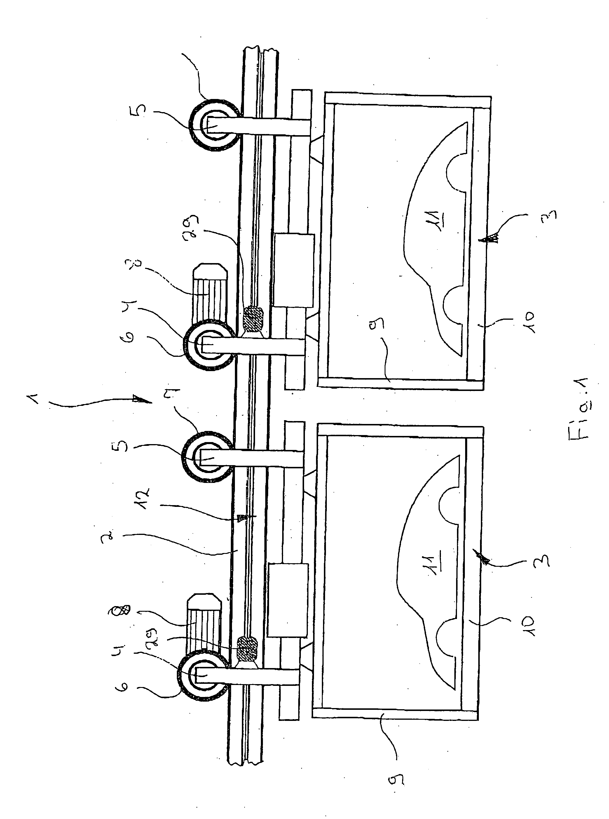
[0021]FIG. 1 shows a section through an electrically powered suspended railway overall with a reference 1. The electrically powered suspended rail system 1 comprises a carrier rail 2, for example held above the floor by a steel construction, on which a number of cars 3 can be driven. Each car 3 has two drive units 4, 5 with wheels 6, 7 which roll along the upper side of the carrier rail 2. Each of the wheels 6 of a drive unit 4 of each car 3 are driven by an electric motor 8.

[0022] From each of the drive units 4,5 on each car 3 a carrier frame 9 is suspended which has a platform 10 for the item to be transported, in the example shown a motor vehicle body 11.

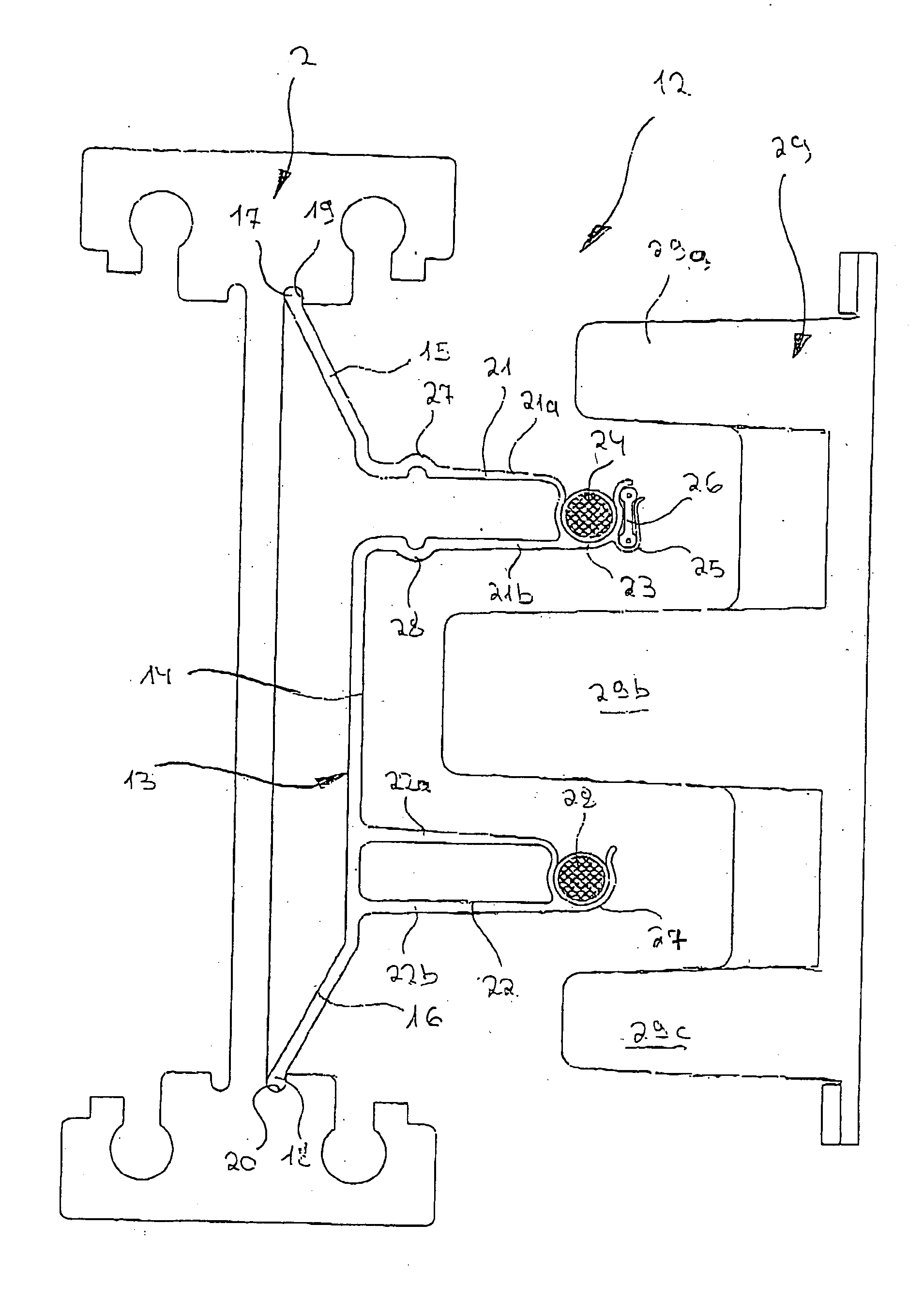
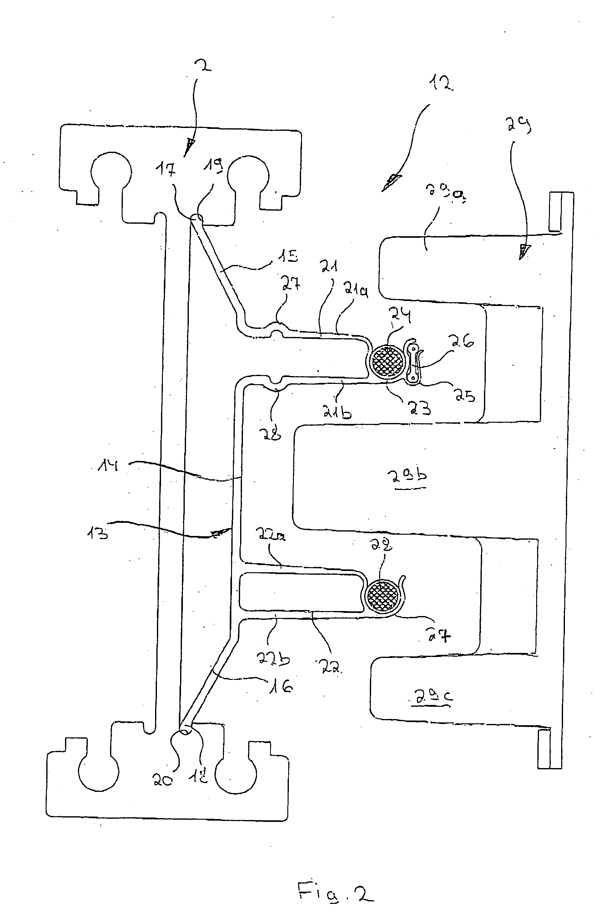
[0023] Along the lateral surface of the carrier rail 2 on the observer's side there is a device for contactless transfer of electrical energy required in particular for operating the electric motors 8 which is referred to overall as 12. A more detailed description of this device 12 is given in FIG. 2. In this, a larger scale se...


PUM


Abstract

A device is described with which electrical energy can be transferred from a power cable running along a stationary rail of a transport system to a moving element that can be driven along the rail. Each moving element has for this purpose a transfer head which works inductively together with the power cable. The power cable is attached with the aid of carrier profile which extends substantially along the entire length of the rail and is fixed in a releasable manner to the rail, which element has at least one a trough-like holder open to the side in which the power cable is laid. The power cable is thus relatively easily and accurately laid, avoiding hanging loops of cable which could be damaged by abrasion by the passing transfer heads of the moving elements.

Description

BACKGROUND OF THE INVENTION [0001] The invention relates to a device for the contactless transfer of electrical energy from at least one power cable carrying electrical energy which is laid alongside a stationary rail of a transport system, to a movable element that can be driven along the rail, which element has a transfer head working inductively together with the power cable, with at least one carrier element fixed in a releasable manner to the rail, which element has a holder for the power cable. [0002] Transport systems of the type considered here are known in various embodiments. One prominent example of this are electrically powered suspension railways in which the individual cars suspended from a carrier rail move along the carrier rail driven by a motor. In all these cases, it is necessary to transfer the electrical energy of the moving element required to operate, in particular to drive it, from a stationary power cable laid alongside the rail, to the movable element. In t...

Claims


Application Information

Patent Timeline
IPC IPC(8): B60L5/00B60L9/00B60M1/30B60M7/00H01F27/30H01F38/14H02J17/00
CPCB60L5/005B60L2200/26B60M1/307
Inventor SWOBODA, WERNERROECKLE, JUERGEN
Owner EISENMANN MASCHENBAU
Why Eureka
Try Eureka