Fastening system with eccentric

a technology of fastening system and eccentric, which is applied in the direction of bolts, manufacturing tools, roads, etc., can solve the problems of increased outlay, inconvenient tightening of screw clamps, and setting the distance between two toothed racks, so as to facilitate re-assembly, increase the rigidity of the connection, and facilitate the effect of re-assembly

Active Publication Date: 2015-02-12
WITTENSTEIN SE
View PDF9 Cites 2 Cited by
  • Summary
  • Abstract
  • Description
  • Claims
  • Application Information

AI Technical Summary

Benefits of technology

[0008]Typical embodiments concern a fastening system for fastening a linear machine element in a machine foundation, having a clamping element which has a shank and a typically circular head. The diameter of said head is normally greater than the diameter of the shank. This permits tightening against the linear machine element. Furthermore, typical embodiments comprise an eccentric which comprises a sleeve with a circular bore which is eccentric with respect to the outer circumference of the sleeve. Furthermore, typical eccentrics comprise a torque-transmitting element. Typical torque-transmitting elements are nuts, hexagonal sockets, Allen connectors or other structures which permit the engagement of a tool for rotating the eccentric about its longitudinal axis. The longitudinal axis is the axis that is typically oriented parallel to the axis of the clamping element. In typical embodiments, as clamping element, use is made of screws or bolts, typically with a head which permits the engagement of a tool for rotating and clamping the clamping element. A typical head comprises an Allen connector or a Torx connector. The outer diameter of the head of the clamping element is typically smaller than the inner diameter of the bore, or typically corresponds at least substantially to the inner diameter of the bore. Mounting of the eccentric on the head is thus made possible. In typical embodiments, the bore is of such a size that the eccentric can be mounted on the head. In some exemplary embodiments, additional adaptation sleeves are provided between the head and the sleeve in order to compensate for the sleeve having an inner diameter that differs from the outer diameter of the head.
[0022]Embodiments yield a time saving during the mounting process and an increase in convenience. Furthermore, by means of typical eccentrics, the pressing action against the machine foundation can be maintained after the mounting process. In embodiments, the eccentrics may be removed after the tightening of the clamping element. As an alternative to remaining in the linear machine element, it is possible, in embodiments, for the eccentric to be removed again after the mounting process and used for further mounting processes. Additional friction forces typically arise between the linear machine element and the machine foundation. This increases security or makes it possible for the clamping elements to be of smaller dimensions. A further advantage may consist in that the linear machine element can be fixed by means of the eccentric by one person. The positioning of a linear machine element relative to an already-mounted linear machine element is possible in a simple and precise manner. Since it is not imperatively necessary for additional bores to be provided in the machine foundation, and the mounting time is shortened, mounting costs are reduced. Since no additional openings are required in the linear machine element for the mounting process, rigidity is not influenced.

Problems solved by technology

Further disadvantages are that it is not possible for any desired number of screw clamps to be provided, that the tightening of the screw clamps can be inconvenient owing to the obstructions posed by the machine foundation, and that the screw clamps restrict access to the screws.
A further problem during the mounting process is the setting of the distance between two toothed racks.
This entails increased outlay and is therefore undesirable.
The large number of parts required can give rise to high production costs and a cumbersome mounting process.

Method used


Image

  • Fastening system with eccentric
  • Fastening system with eccentric
  • Fastening system with eccentric

Examples


Embodiment Construction

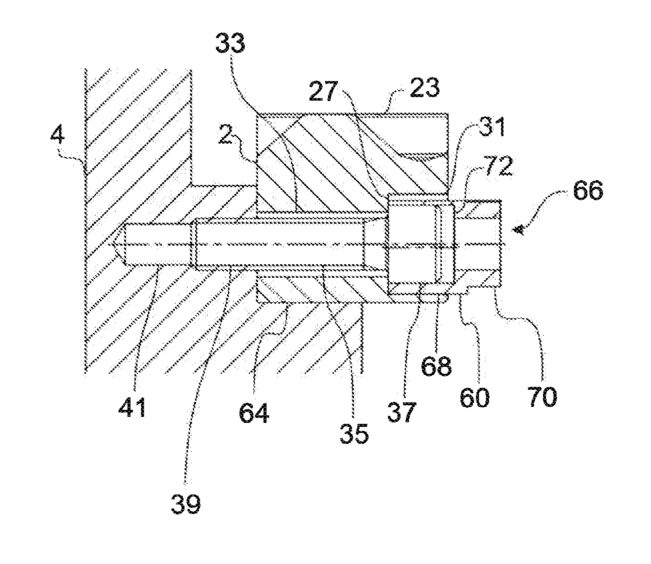
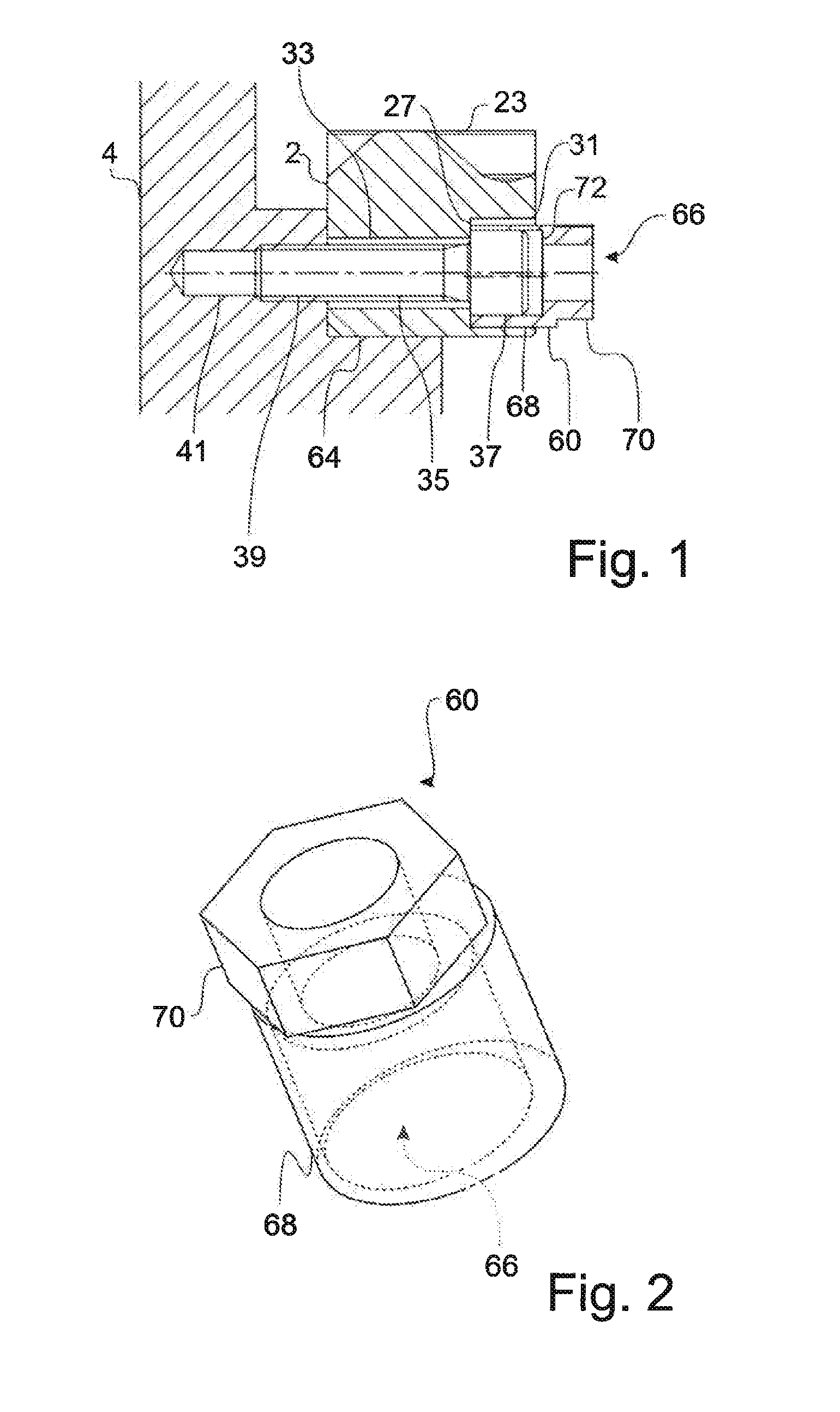
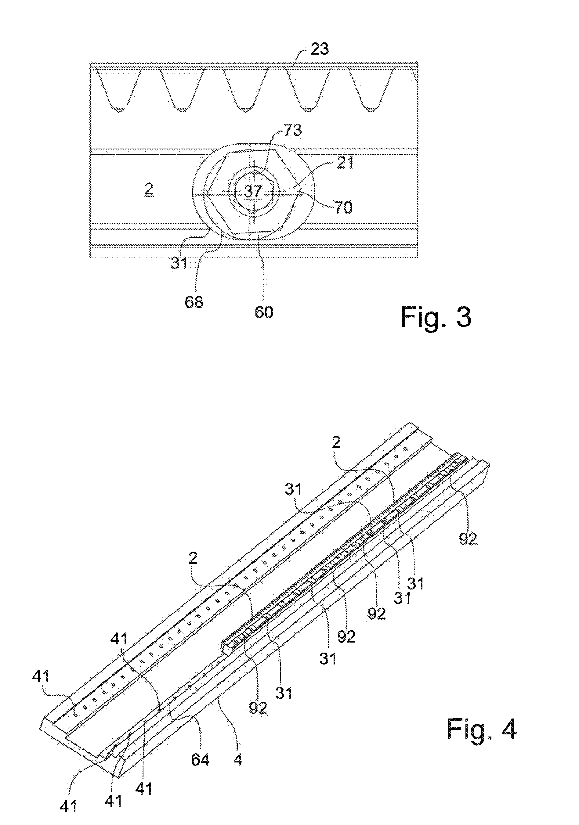
[0031]Typical embodiments will be described below on the basis of the figures, wherein the invention is not restricted to the exemplary embodiments; the scope of the invention is rather defined by the claims. FIGS. 1-7 show typical embodiments or parts of typical embodiments. For the description of all of the figures, the same reference signs will be used for corresponding parts and will not be described repeatedly in conjunction with each individual figure. Some features or parts are identical in the various embodiments and will not be repeatedly explained in detail.

[0032]FIG. 1 shows, in a cross section, a cross section through an embodiment of a fastening system for the fastening of a linear machine element. In the embodiment of FIG. 1, a linear machine element 2 in the form of a toothed rack is provided.

[0033]The linear machine element 2 comprises a toothing 23 which is of oblique form. Also visible in the cross section of FIG. 1 is an opening which extends through the linear ma...


PUM

PropertyMeasurementUnit
diameteraaaaaaaaaa
diameteraaaaaaaaaa
diameteraaaaaaaaaa

Abstract

Fastening system for a linear machine element (2, 102) for fastening in a machine foundation (4), having a clamping element which has a shank (35) and a head (37), wherein the diameter of the head (37) is greater than the diameter of the shank (35), and having an eccentric (60) which comprises a sleeve (68) with an eccentric bore (66) and a torque-transmitting element (70), wherein the outer diameter of the head (37) is smaller than the inner diameter of the bore (66) or at least substantially corresponds to the inner diameter of the bore (66).

Description

BACKGROUND OF THE INVENTION[0001]The invention relates to a fastening system for a linear machine element and to an eccentric, a linear machine element and a method for the fastening of a linear machine element.[0002]For the mounting of linear machine elements, in particular toothed racks or linear guides, it is important for the machine elements to be pressed against a machine foundation, and oriented correctly, over the entire length. This is necessary in particular in high-precision applications. From the prior art, methods are known in which a machine element is pressed against the machine foundation by means of a screw clamp and subsequently fixed by means of screws. This is an iterative process because toothed racks, for example, can be pressed on only over a short distance by means of a screw clamp. When the toothed rack has been fastened at that location, the screw clamp at the next location is tightened in order to fix the toothed rack again there. Further disadvantages are...

Claims


Application Information

Patent Timeline
Patent Type & Authority Applications(United States)
IPC IPC(8): F16B19/02F16B21/02
CPCF16B19/02F16B21/02F16B5/02F16C29/004F16C2322/39F16H55/26Y10T29/49948
Inventor ENDRES, JOCHENHECKMANN, MARCO
Owner WITTENSTEIN SE
Why Eureka
Try Eureka