Apparatus for dispensing free-flowing material

Inactive Publication Date: 2005-05-12
NORDSON CORP
View PDF13 Cites 18 Cited by
  • Summary
  • Abstract
  • Description
  • Claims
  • Application Information

AI Technical Summary

Benefits of technology

[0007] An advantage of the invention is that the drive shaft for driving the pump is radially detachable from the coupling and can also be inserted radially into the coupling during assembly. Assembly and disassembly are thus considerably simplified, because it is no longer necessary to disassemble the entire drivetrain comprising the drive motor, the coupling and the pump. Instead, the coupling can be simply detached.
[0008] According to another aspect of the invention or a preferred embodiment thereof, it is proposed that the coupling be configured in such a way that an axial offset and/or an angled offset is possible during operation between a shaft of the drive motor and the drive shaft for driving the pump. Assembly and disassembly are further simplified with such a coupling because precise alignment of the shaft of the pump and the drive motor is no longer necessary

Problems solved by technology

A number of problems arise as a result of this arrangement.
When assembling the pump, the coupling and the drive motor, it is necessary to ensure at all times that the drive shaft of the drive motor and the drive shaft of the pump are precisely aligned with each other, which is a time-consuming affair and often almost impossible due to the manufacturing tolerances of the components and fixing elements.
Furthermore, thermally induced effects brought about by the relat

Method used


Image

  • Apparatus for dispensing free-flowing material
  • Apparatus for dispensing free-flowing material
  • Apparatus for dispensing free-flowing material

Examples


Embodiment Construction

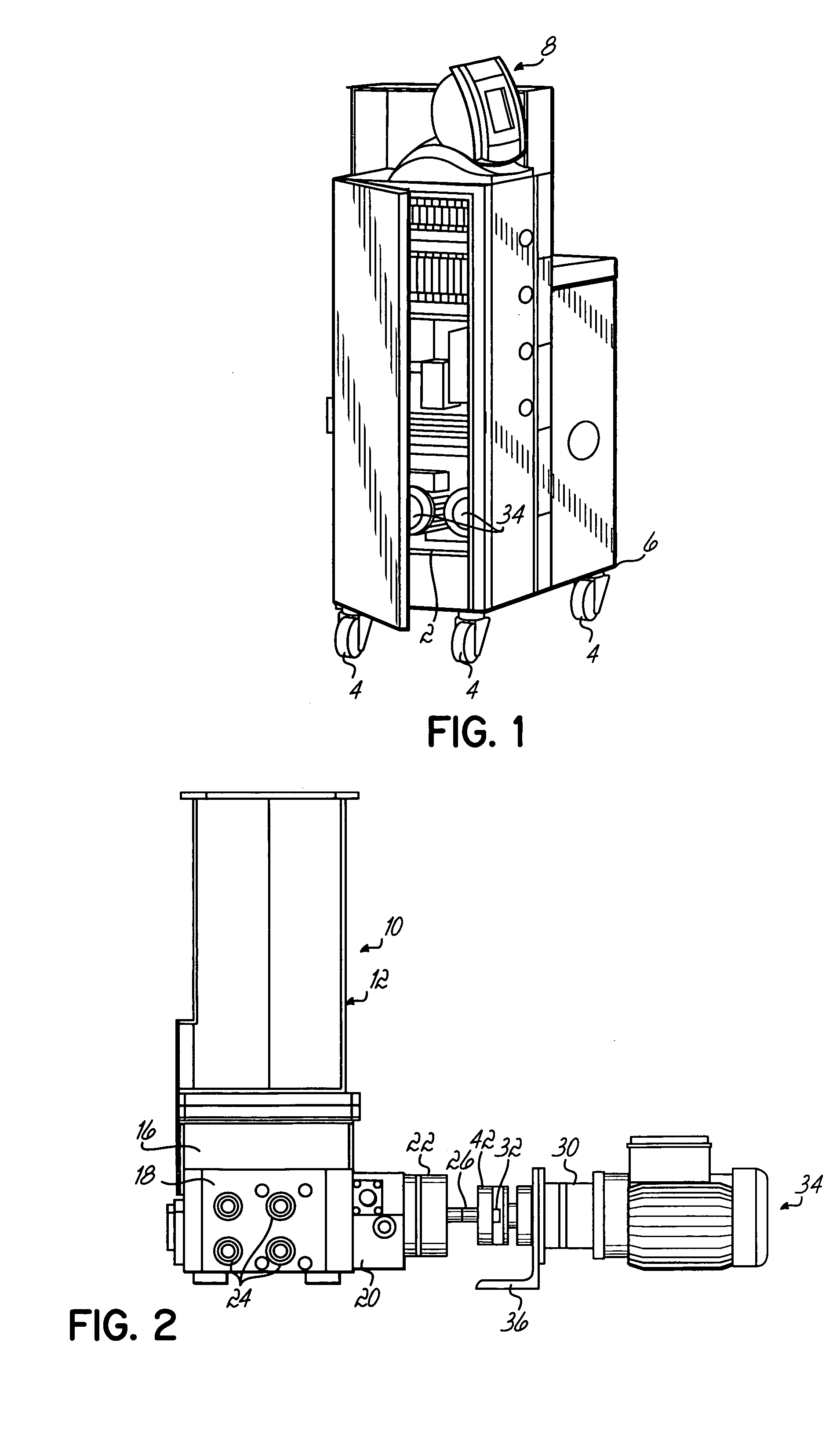
[0017] The preferred embodiment shown in the Figures is an apparatus for dispensing thermoplastic material, in particular hot melt adhesive. The separate components of the apparatus are supported by a frame 2 that can be moved by a total of four rollers 4. Each roller is attached to one corner of a parallelepipedal base 6 of frame 2. Also attached to frame 2 are outer walls and doors, as well as a control and regulation unit 8 with an operating and display panel 8.

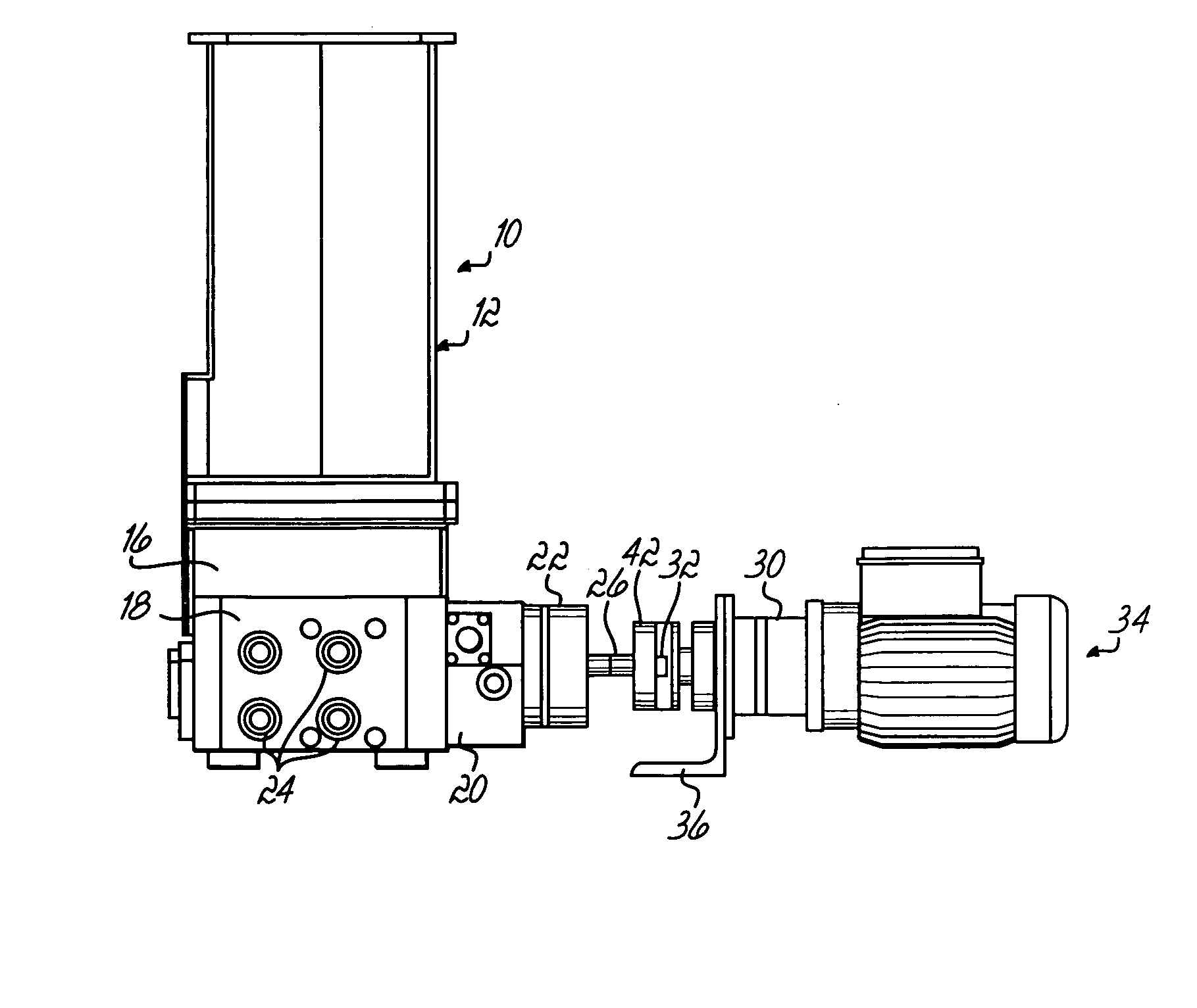
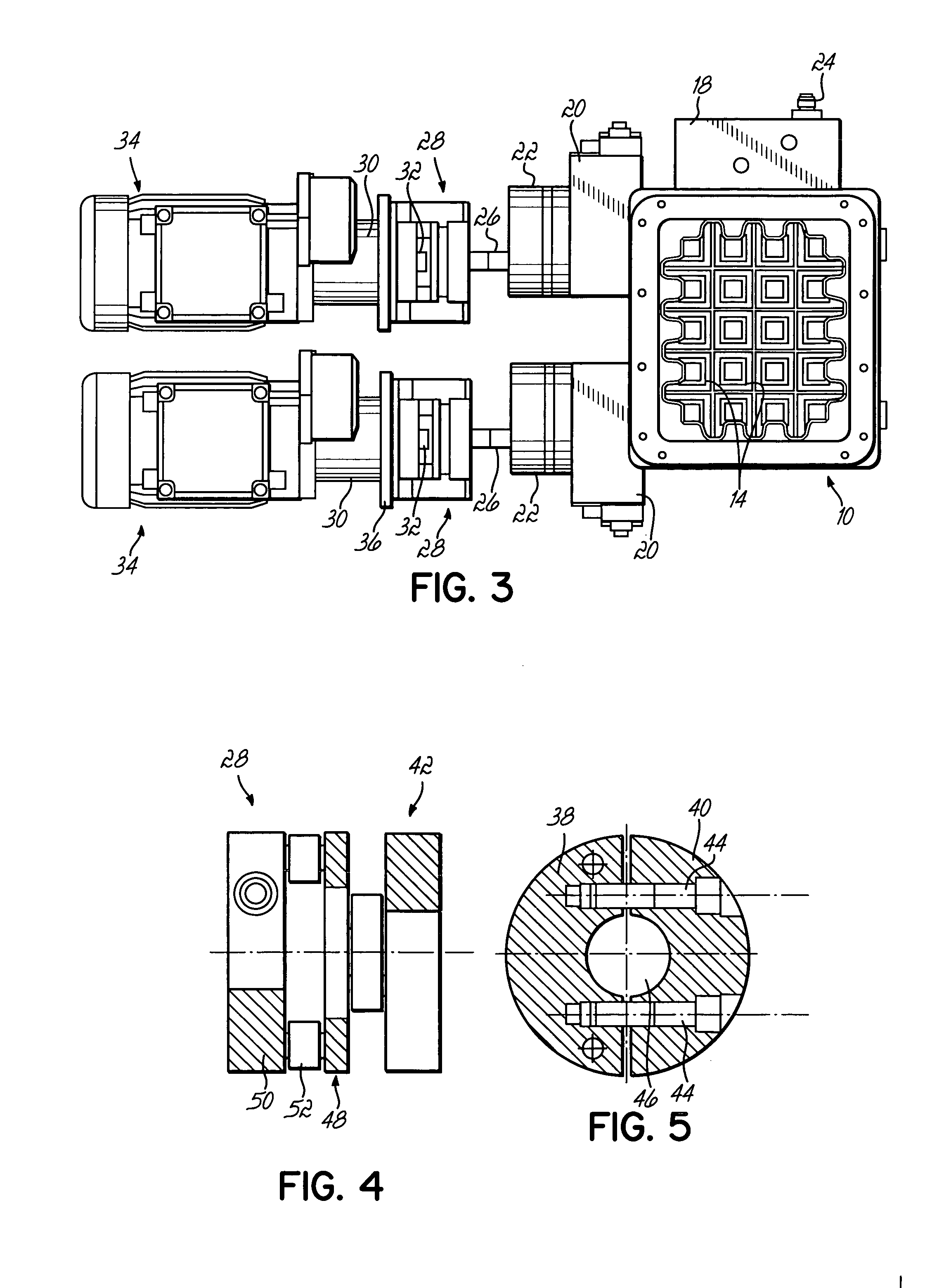
[0018] As FIGS. 2 and 3 show, a container 10 for receiving the material is disposed inside a portion of the apparatus—on the right in FIG. 1—and can be filled through an upper inlet opening with the material, which can initially be in a solid state, for example in the form of pellets or the like. An electrically heated grid 14 is disposed in an upper pre-heating area 12 of container 10 (see FIG. 3). An electrically heatable melter group 16 is also disposed in the lower portion of the container 10. The melter group 16 incl...


PUM

PropertyMeasurementUnit
Melting pointaaaaaaaaaa

Abstract

Apparatus for dispensing a free-flowing material comprising a container for receiving the material, a pump connected to the container for conveying the material to a port from which free-flowing material can be dispensed. The pump includes at least one rotatable pump element and a rotatable drive shaft coupled to the pump element, a drive motor, and a coupling attached between the drive shaft and the drive motor. The coupling is radially detachable from the drive shaft.

Description

FIELD OF THE INVENTION [0001] The present invention relates to a device for dispensing free-flowing material and, in particular for dispensing thermoplastic material. BACKGROUND OF THE INVENTION [0002] Devices of this kind for dispensing material, in particular thermoplastic material such as hot melt adhesive, are known in various embodiments. For example, in one embodiment the material to be dispensed is first filled into the container in a solid state, and then melted to a free-flowing state. The free-flowing material is then channeled from the container to a pump and from there to a connection point that can be connected to at least one tube for further conveying the molten material. [0003] The container, the pump and the drive motor are mounted onto the frame or rack of the apparatus in such a way that the pump, the coupling and the drive motor are arranged in series underneath the container and housed inside a cabinet attached to the frame. [0004] A number of problems arise as ...

Claims


Application Information

Patent Timeline
IPC IPC(8): F16D1/02B05C5/04B29B13/02F04C13/00F04C15/00F16D3/02F16D3/78H02K7/116H02K16/00
CPCB29B13/022F04C13/002F16D3/78F16D3/02F04C15/0061
Inventor DITTMANN, RALFLUGER, ALFREDMENEKSE, MUENUER
Owner NORDSON CORP
Why Eureka
Try Eureka