
Automotive audio controller with vibration sensor

a technology of vibration sensor and automotive audio, which is applied in the direction of frequency response correction, instruments, transportation and packaging, etc., can solve the problems of increasing the gain in response, painfully loud for a listener, and problems such as the problem of automotive audio reproduction system, and achieve the effect of increasing the gain level of the audio signal

Active Publication Date: 2005-05-12
HARMAN INT IND INC
View PDF21 Cites 31 Cited by
  • Summary
  • Abstract
  • Description
  • Claims
  • Application Information

AI Technical Summary

Benefits of technology

[0011] An automotive audio controller is provided for receiving an audio signal from an audio source and providing a filtered audio signal that compensates for ambient noise in the automobile. The audio controller may have a vibration sensor that generates a vibration signal indicative of vibrations in the automobile. A dynamic filter of the audio controller may receive the vibration signal and the audio signal, and change the gain level and / or tone of the audio signal based on the vibration signal to generate the filtered audio signal. For example, the dynamic filter may increase the gain level of the audio signal as the vibration signal increases to generate the filtered audio signal.

Problems solved by technology

Therefore, audio reproduction systems designed to operate in noisy environments, such as inside an automobile, often contain components that attempt to compensate for perceived degradation of the audio signal caused by noise.
This low frequency ambient noise causes problems for automotive audio reproduction systems.
Listeners may wish to maintain the apparent volume at a constant level, but this is difficult as the ambient noise changes dynamically in an automobile, for example, because of changing road conditions and / or changing automobile speeds.
However, the method may be disadvantageous because it varies the gain irrespective of the volume level set by the user, so the method increases the gain in response to increasing noise even for very high volume levels.
These increases may result in producing signals that are painfully loud for a listener, harmful to the audio reproduction equipment, or both.
This causes the signals to lose their desired tone.
This method, however, may generate a signal that represents only the sub-audio low-frequency noise, rather than the actual masking noise that may contain higher frequencies.
This method may be disadvantageous because it involves the transfer function from the speakers of the audio reproduction system to the microphone.
The transfer function may be difficult to determine, and, moreover, may vary dynamically, for example, with changes in the number of passengers in the automobile.
Furthermore, using a microphone in the passenger compartment of the automobile may cause increases in the signal in response to speech of passengers, so that the audio reproduction system may attempt to “drown out” conversations.
Many of these complex systems are not economically feasible for use in mass produced automobiles.
None of these prior systems provides both an economically viable and satisfactory sounding solution.

Method used


Image

  • Automotive audio controller with vibration sensor
  • Automotive audio controller with vibration sensor
  • Automotive audio controller with vibration sensor

Examples


Embodiment Construction

[0023] First Automotive Audio Controller

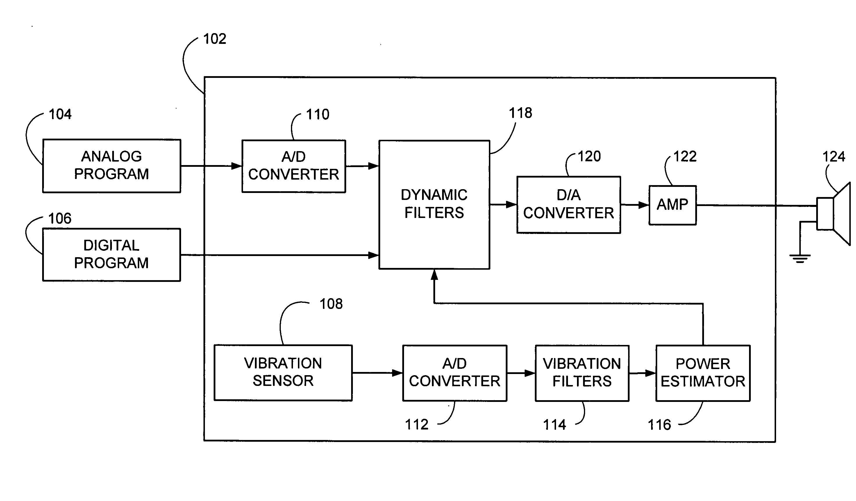
[0024] A first example automotive audio controller 102 for use in an automobile is shown in FIG. 1. The term “automotive audio controllers” as used herein refers to items known in the vernacular as “car stereos” or “car stereo components.” Automotive audio controllers are frequently installed in most types of motorized vehicles. The term “automobile” as used herein refers to motorized vehicles, such as motorcycles, boats, fixed or rotary wing aircraft, or any other vehicles that have an engine and transport passengers. The term “passenger compartment” is used herein to refer to a space in or on a vehicle that is occupied by passengers, such as the cabin of a car or an aircraft, or the space generally between the handlebars and the taillight of a motorcycle.

[0025] The automotive audio controller 102 may be coupled to an analog audio source 104, a digital audio source 106, and at least one speaker 124. The automotive audio controller 102 may b...


PUM

PropertyMeasurementUnit
cutoff frequencyaaaaaaaaaa

Abstract

An automotive audio controller is provided for receiving an audio signal from an audio source and providing a filtered audio signal that may help compensate for ambient noise in the automobile. The audio controller may have a vibration sensor that generates a vibration signal indicative of vibrations in the automobile. A dynamic filter of the audio controller may receive the vibration signal and the audio signal, and change the gain level and / or tone of the audio signal based on the vibration signal to generate the filtered audio signal. The audio controller also may receive a speed signal, and change the gain level and / or tone of the audio signal based on the speed signal to generate the filtered audio signal.

Description

BACKGROUND OF THE INVENTION [0001] 1. Technical Field [0002] This invention relates to a sound system for an automobile, and more particularly, to a sound system capable of dynamically adjusting gain and tone characteristics for a reproduced audio signal in accordance with a vibration level in the automobile. [0003] 2. Related Art [0004] Human perception of acoustic signals, such as an audio signal (music, speech, etc.) generated by an audio reproduction system, is affected by the presence of ambient noise. Therefore, audio reproduction systems designed to operate in noisy environments, such as inside an automobile, often contain components that attempt to compensate for perceived degradation of the audio signal caused by noise. [0005] Ambient noise in automobiles, caused by, for example, the engine or the interaction of the tires and the road surface, may not be band-limited but usually has strong components below approximately 200 Hz. This low frequency ambient noise causes proble...

Claims


Application Information

Patent Timeline
Patent Type & Authority Applications(United States)
IPC IPC(8): B60R11/02G10K11/178G11B20/10H03G3/32H04R3/00H04R3/04
CPCH04R3/04H03G3/32G11B20/10
Inventor EID, BRADLEY F.MCCORKLE, DAVID P.DZOMBAK, IVAN GREGORY
Owner HARMAN INT IND INC
Learn More