Fastener assembly

Inactive Publication Date: 2005-05-12
WU HUNG MING
View PDF12 Cites 23 Cited by
  • Summary
  • Abstract
  • Description
  • Claims
  • Application Information

AI Technical Summary

Benefits of technology

[0007] Therefore, the object of this invention is to provide a fastener assembly which is capable of overcoming the aforesaid disadvantages of the prior art.
[0008] According to the present invention, the fastener assembly includes: a protective cover and a fastening member. The protective cover includes an annular part, a cap, and a connecting strip interconnecting elastically the annular part and the cap. The annular part defines a through-hole. The fastening member includes a head with a bottom end, a retention flange extending radially and outwardly from the bottom end of the head, an abutting fla

Problems solved by technology

The aforesaid conventional fastener assembly is disadvantageous in that the annular part 132 of the protective cover 13 tends to twist and break upon tightening of the fastening member 11 and that the position of the annular part

Method used


Image

  • Fastener assembly
  • Fastener assembly
  • Fastener assembly

Examples


Example

[0015] Before the present invention is described in greater detail with reference to the following preferred embodiments, it should be noted that same reference numerals have been used to denote similar elements throughout the specification.

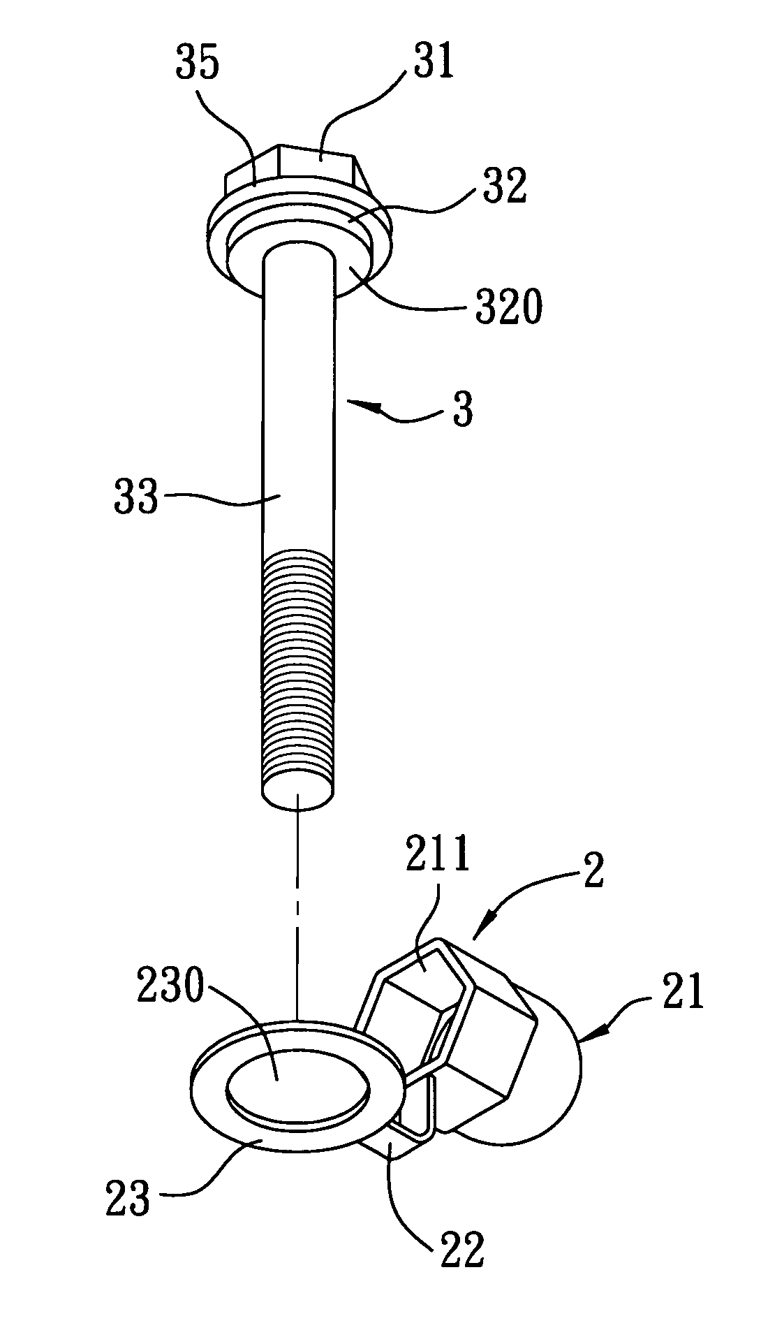
[0016] Referring to FIG. 3, the first preferred embodiment of a fastener assembly according to the present invention is shown to include a protective cover 2 and a fastening member 3.

[0017] The protective cover 2 is made from elastic material, and includes an annular part 23, a cap 21 with a polygonal portion 211, and a connecting strip 22 interconnecting elastically the annular part 23 and the polygonal portion 211 of the cap 21. The annular part 23 defines a through-hole 230.

[0018] The fastening member 3 is made from metal, and includes a polygonal head 31 with a bottom end, a retention flange 35 that extends radially and outwardly from the bottom end of the head 31, an abutting flange 32 that is reduced in diameter and that extends co-axial...


PUM


Abstract

A fastener assembly includes a protective cover having an annular part, a cap, and a connecting strip interconnecting elastically the annular part and the cap. A fastening member has a head, a retention flange extending radially and outwardly from a bottom end of the head, an abutting flange that is reduced in diameter and that extends co-axially from the retention flange, and a screw rod that is reduced in diameter and that extends co-axially from the abutting flange. The abutting flange has a thickness greater than that of the annular part of the cover and a diameter smaller than that of a through-hole in the annular part of the cover. The retention flange has a diameter greater than that of the through-hole in the annular part of the cover.

Description

BACKGROUND OF THE INVENTION [0001] 1. Field of the Invention [0002] The present invention relates to a fastener assembly, more particularly to a fastener assembly with a fastening member and a protective cover that is freely rotatable relative to the fastening member when coupled to the fastening member. [0003] 2. Description of the Related Art [0004] Referring to FIG. 1, a conventional fastener assembly is shown to include a protective cover 13 and a fastening member 11. The protective cover 13 includes an annular part 132 defining a through-hole 135, a cap 131, and a connecting strip 133 interconnecting elastically the annular part 132 and the cap 131. The fastening member 11 includes a head 111 with a bottom end, an abutting flange 113 extending radially and outwardly from the bottom end of the head 111, and a screw rod 112 that is reduced in diameter and that extends co-axially from the abutting flange 113. The abutting flange 113 has a diameter greater than that of the through-...

Claims


Application Information

Patent Timeline
IPC IPC(8): F16B37/14
CPCF16B37/14
Inventor WU, HUNG-MING
Owner WU HUNG MING
Why Eureka
Try Eureka