

Bone screws
a technology of bone screws and screws, applied in the field of bone screws, can solve the problems of many types of heads that are unsuitable for achieving sufficient purchase, difficult placement of bone screws with varying pitch, damage to bone,
- Summary
- Abstract
- Description
- Claims
- Application Information
AI Technical Summary
Problems solved by technology
Method used
Image

Examples
example 1
Bone Screw with a Stepped Head
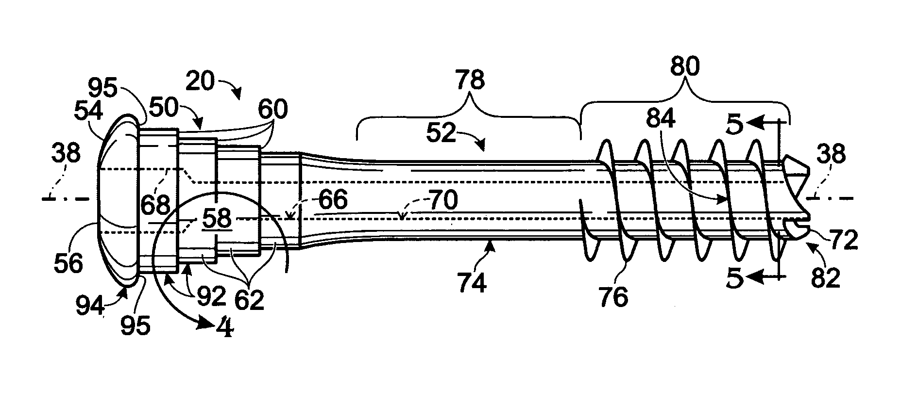
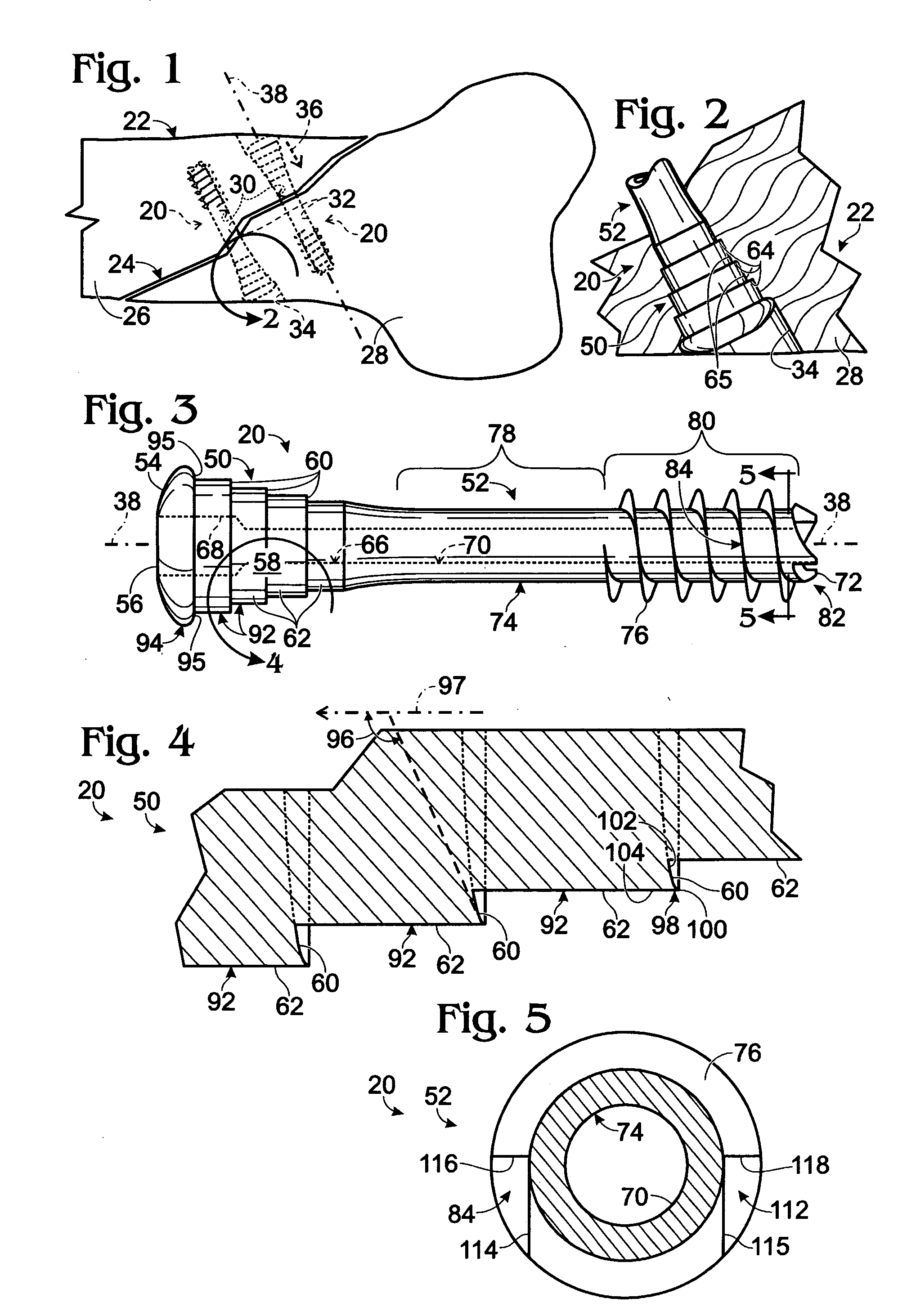
[0047] This example describes an exemplary bone screw 20 having a stepped head 50; see FIGS. 1-5. The bone screw includes a stepped head 50 and a shank 52 joined, in this embodiment, fixedly to one another. Aspects of this screw were discussed above, at the beginning of the Detailed Description, particularly in the context of FIGS. 1-3.
[0048]FIG. 4 shows a partial sectional view of a portion of stepped head 50 (see FIGS. 1-3 for a full view). Stepped head 50 may be defined by a plurality of cylindrical head segments 92 and an optional cylindrical or noncylindrical most proximal segment 94 that is greater in diameter than head segments 92. Some or all of the head segments may decrease in diameter stepwise toward the shank.
[0049] Head segments 92, 94 may define ledge structures 60, 95, respectively. For example, head segments 92 each may define a ledge structure 60 at their distal or leading edge and a cylindrical surface region 62 proximal to or trail...
example 2
Bone Screws with Annular Grooves
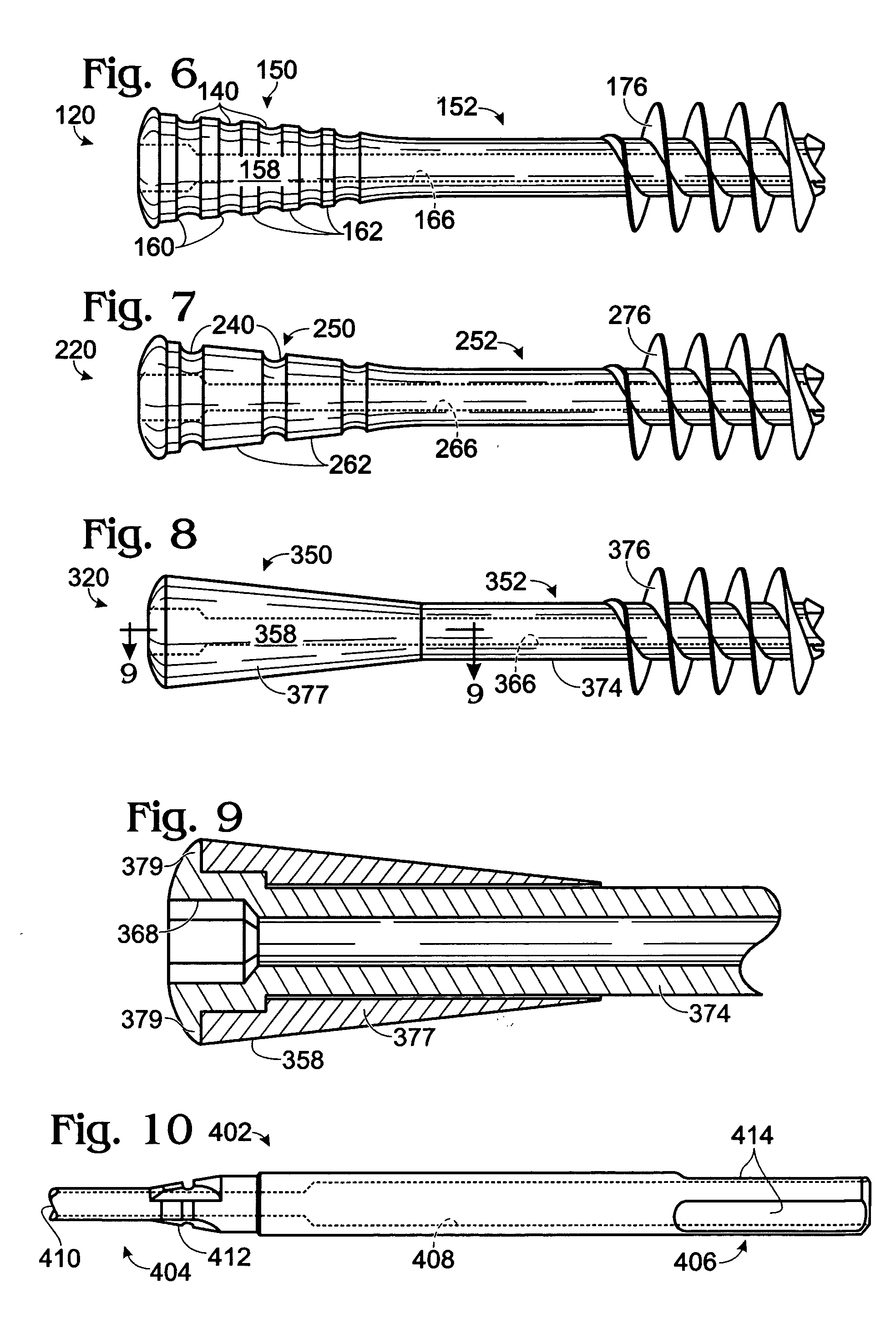
[0052] This example describes bone screws 120 and 220 having a plurality of annular grooves disposed on the head; see FIGS. 6-7. For convenience, features of these bone screws have been assigned numerical labels that correspond (in the ones and tens) to those of corresponding features of bone screw 20 in FIGS. 1-5. Thus, for example, heads 150, 250, shanks 152, 252, axial bores 166, 266, and threads 176, 276 of bone screws 120, 220 correspond at least approximately to head 50, shank 52, axial bore 66, and thread 76 of bone screw 20, respectively.
[0053]FIG. 6 shows exemplary bone screw 120. Bone screw 120 may include ledge structures 160 created by annular grooves 140 in head 150. Grooves 140 may be defined in lateral surface 158 by depressions in the head flanked by surface regions 162. The ledge structures may be defined by the trailing or proximal sides of each groove 140. In alternative embodiments, the grooves may be configured as ridges that ex...
example 3
Bone Screw with Rotatable Head
[0055] This example describes a bone screw having a rotatable head; see FIGS. 8-9. For convenience, features of this bone screw have been assigned numerical labels that correspond (in the ones and tens) to those of corresponding features of bone screw 20 in FIGS. 1-5. Thus, for example, head 350, axial bore 366, tool engagement structure 368, and threads 376 of bone screw 320 correspond at least approximately to head 50, axial bore 66, tool engagement structure 68, and thread 76 of bone screw 20, respectively.
[0056]FIGS. 8 and 9 show exemplary bone screw 320. Head 350 of bone screw 320 may be coupled rotatably to shank 352. In particular, in this embodiment, some or all of the lateral surface 358 of the head may rotate in relation to shaft 374. Head 350 may include a sleeve 377 through which shaft 374 extends. Shaft 374 may widen proximally to define a flange 379 that restricts axial movement of the sleeve in a proximal direction (see FIG. 9). Flange ...
PUM
 Abstract
Description
Claims
Application Information