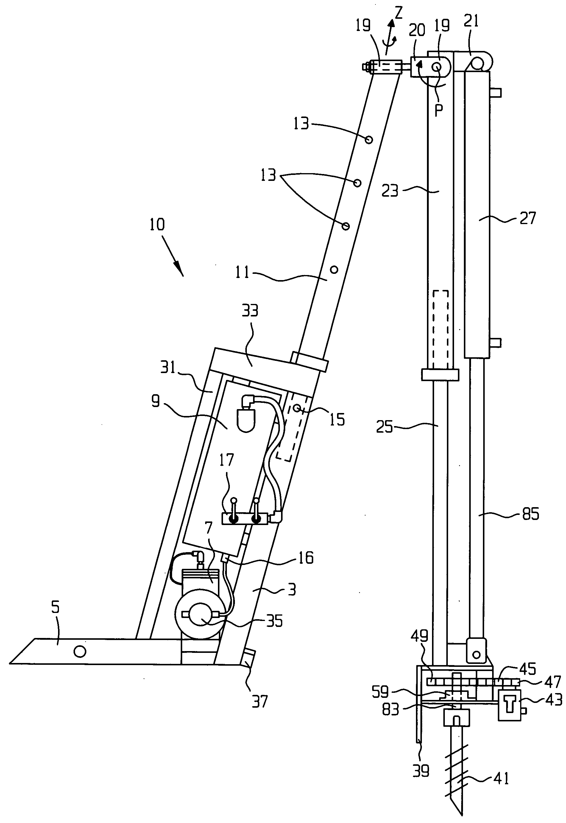
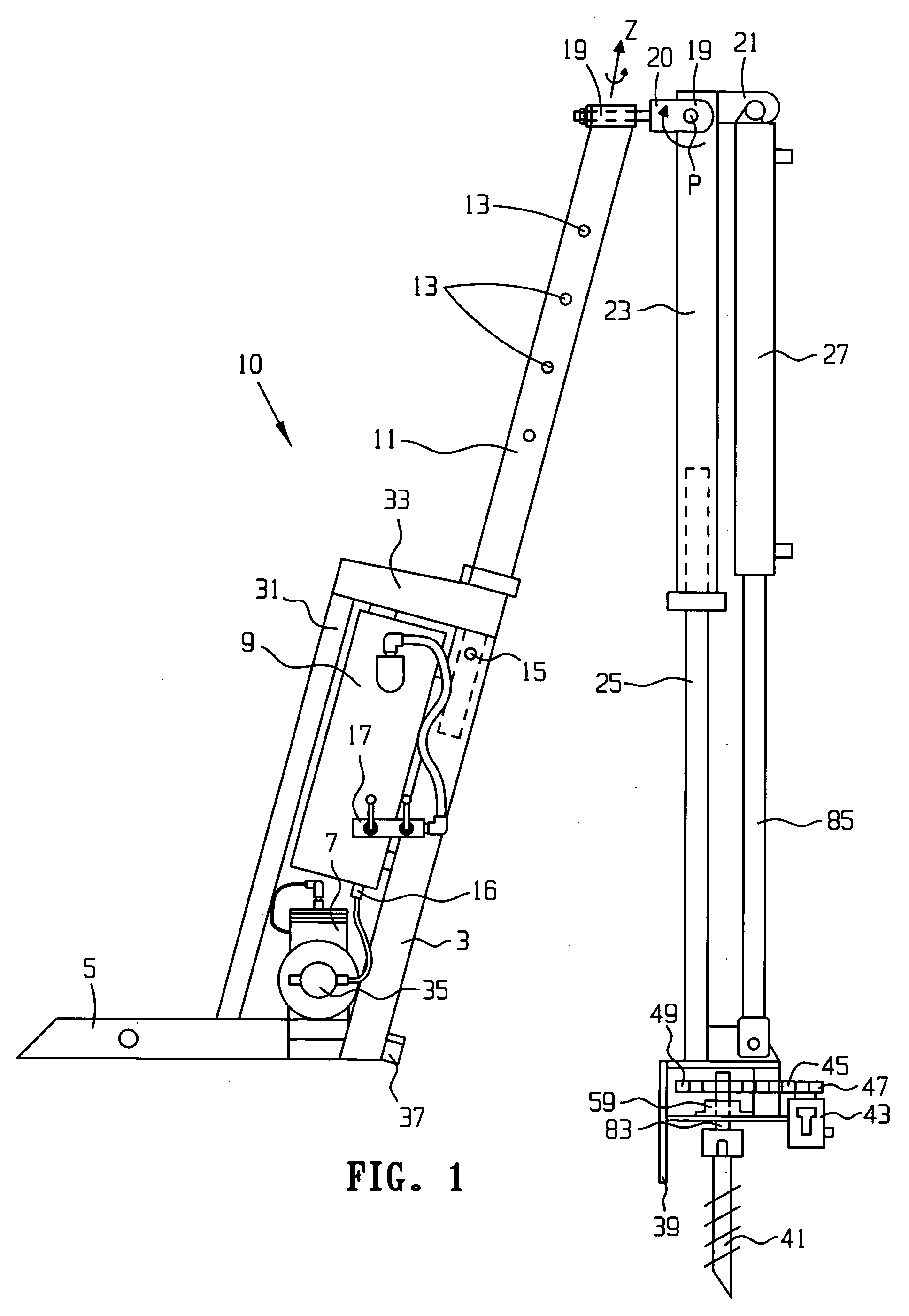
[0005] The present invention provides a device useful for drilling holes in the earth, and it comprises a horizontal frame member having a first end portion and a second end portion. There is a vertically inclined tubing casing having a first end portion, an open second end portion, a length dimension, and a hollow interior portion, wherein the first end portion of the vertically inclined tubing casing is attached to the second end portion of the horizontal frame member. The vertically inclined tubing casing further comprises a hole disposed through it along its length, the hole having an axis, wherein the axis of the hole is substantially perpendicular to the length dimension of the vertically inclined tubing casing. There is also a vertically inclined brace portion having a first end portion, a second end portion and a length dimension, and the first end portion of the vertically inclined brace is attached to the horizontal frame member at a location between the first end portion of the horizontal frame member and the second end portion of the horizontal frame member, such that the length dimension of the vertically inclined brace portion and the length dimension of the vertically-inclined tubing casing are substantially parallel to one another. There is also an adjustable height support having a first end portion, a second end portion, a length dimension, and a length dimension axis, and the first end portion of the height support and at least a portion of the length of the height support is slidably disposed within the vertically inclined tubing casing. The height support further comprises a plurality of holes disposed through it along its length, and these holes each have an axis, and their axes are substantially perpendicular to the length dimension of the height support. There is a two-axis hinge which is hingedly connected to the second end portion of the height support, and the two-axis hinge has a degree of freedom which enables its rotational movement about the length dimension axis of the height support. There is also a substantially linear vertical guide outer member having a first end portion, an open second end portion, and a length dimension, and the first end portion of the vertical guide outer member is pivotally connected to the height support by means of the two-axis hinge such that the vertical guide outer member is given a sufficient degree of freedom to rotate rendering its second end portion capable of striking out an arc which intersects the adjustable height support at a point along the length of the height support. There is a hydraulic ram having a hydraulic oil inlet, a hydraulic oil outlet, a length dimension, a first end portion disposed at the end of its stationary portion, and a second end portion disposed at the end of its moveable portion, and the hydraulic ram is attached to the vertical guide outer member such that the length dimension of the hydraulic ram and the length dimension of the vertical guide outer member are substantially parallel to one another. There is a substantially linear vertical guide inner member having a first end portion, a second end portion and a length dimension, and at least a portion of the first end portion of the vertical guide inner member is slidably disposed within the vertical guide outer member. The invention further includes a drilling head attached to the second end portion of the hydraulic ram and the second end portion of the vertical guide inner member, and an engine having an output shaft, wherein the engine is mounted to at least one of the horizontal frame member, the vertically inclined tube casing, or the vertically inclined brace portion. There is a hydraulic pump having an input shaft, and the input shaft of the hydraulic pump is in effective mechanical communication with the output shaft of the engine. The invention further includes a hydraulic oil reservoir, and a means for providing hydraulic fluid under pressure from the hydraulic pump to the hydraulic ram.
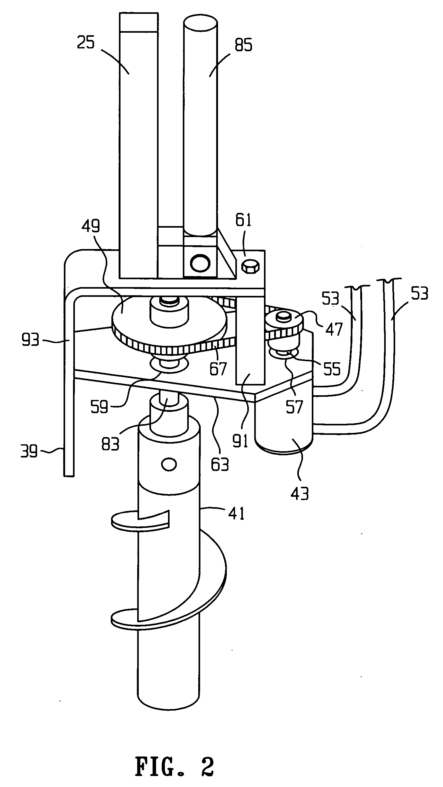
[0006] According to one embodiment, the drilling head comprises: i) a top plate portion; ii) a bottom plate portion having a first hole and a second hole disposed through it; iii) a hydraulic motor having a drive shaft, wherein the hydraulic motor is mounted to the bottom plate portion such that the drive shaft passes through the first hole in the bottom plate portion; iv) a first sprocket disposed on the drive shaft; v) a drilling shaft having a first end portion and a second end portion, the first end portion of the drilling shaft having a second sprocket disposed thereon, the drilling shaft being mounted through the second hole in the bottom plate portion by means of a bearing; vi) a motion communicator, selected from the group consisting of: chains and belts, in contact with each of the first sprocket and the second sprocket; vii) an auger bit having a length dimension, attached to the second end portion of the drilling drive shaft such that the length dimension of the auger bit is substantially parallel to the length dimension of the vertical guide inner member; and viii) means for providing hydraulic fluid under pressure from the hydraulic pump to the hydraulic motor. Preferably, the means for providing hydraulic fluid under pressure from the hydraulic pump to the hydraulic motor comprises a hydraulic conduit disposed between the outlet of said hydraulic pump and the inlet of said hydraulic motor. Preferably, this hydraulic conduit includes a valve means disposed along its length for selectively controlling the flow of hydraulic fluid. In addition, it is preferred that there is a hydraulic conduit for transferring hydraulic oil under low pressure from the outlet of the hydraulic motor to the reservoir.
