High capacity load decorative floor display rack

a technology for display racks and floor displays, which is applied to display racks, show hangers, and display shelves, etc., can solve the problems of inability to meet the needs of retail customers, the decorative covering itself may crack or shear under such loads, and the cost of sacrificing the aesthetics of display racks in order to increase the load bearing capacity of display racks, etc., to achieve high capacity load bearing, support vertical and horizontal loading, and high capacity

Inactive Publication Date: 2005-05-19
JP METAL AMERICA
View PDF2 Cites 3 Cited by
  • Summary
  • Abstract
  • Description
  • Claims
  • Application Information

AI Technical Summary

Benefits of technology

[0007] A decorative retail merchandise floor display rack capable of bearing high capacity hanging loads includes a pair of spaced apart substantially parallel vertically extending slab side decorative panels, such as wooden panels, which each include a vertically extending structural steel criss-crossed supportg framework hidden inside which is capable of supporting vertical and horizontal loading on the display rack. The framework includes both horizontally extending and vertically extending mounting sockets for enabling the display rack components to be structurally tied together. A removable decorative covering for the slabs is provided which is also structurally tied into the display rack. Horizontally extending tubular steel hanging rods extend between the decorative panels for supporting hanging loads thereon, with steel rod like member extending through the horizontally extending tubular steel hanging rods and into the mounting sockets in the supporting framework where they are structurally tied in to the framework. A horizontally extending steel rod base member is spaced below the hanging rod members and extends substantially parallel thereto and is structurally tied to the supporting framework through the vertically extending mounting sockets for providing open box like supporting structure including the decorative slabs and the supporting framework to provide an integrally connected high capacity load bearing decorative retail merchandise floor display rack.

Problems solved by technology

These prior art solutions, however, keep the aesthetic aspect and the structural aspect of the display rack components separate and distinct from each other, using different components solely for each of these aspects, thereby sacrificing features of one for the other and resulting in an inefficient use of materials.
As a result, in certain instances, not only is the display rack itself not strong enough to bear the desired loads, but the decorative covering itself may crack or shear under such loads.
Attempting to solve this problem by sacrificing the aesthetics of the display rack in order to increase the load bearing capacity of the display rack is not a viable solution in a retail environment, particularly a high-end retail environment, as it defeats the essential marketing purpose of displaying the merchandise in an attractive manner.

Method used


Image

  • High capacity load decorative floor display rack
  • High capacity load decorative floor display rack
  • High capacity load decorative floor display rack

Examples


Embodiment Construction

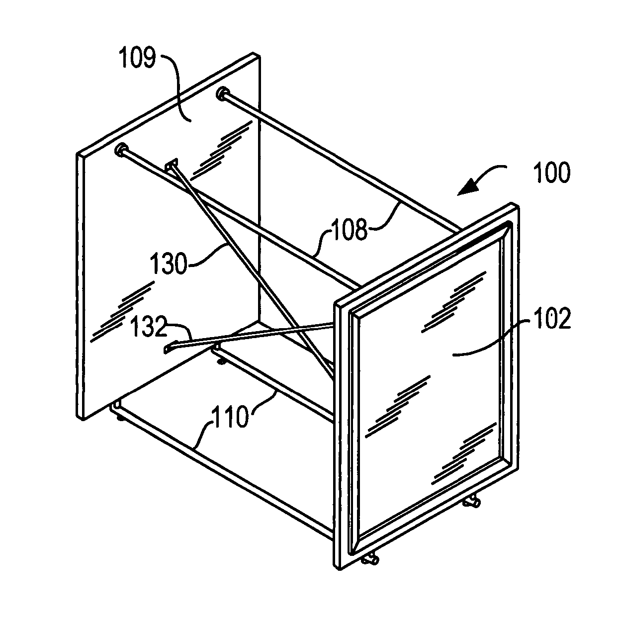
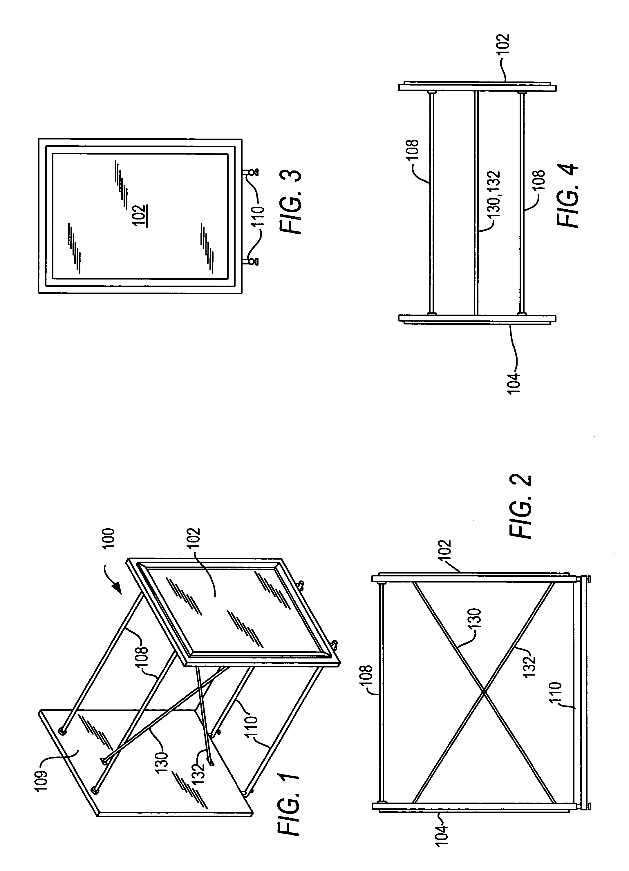
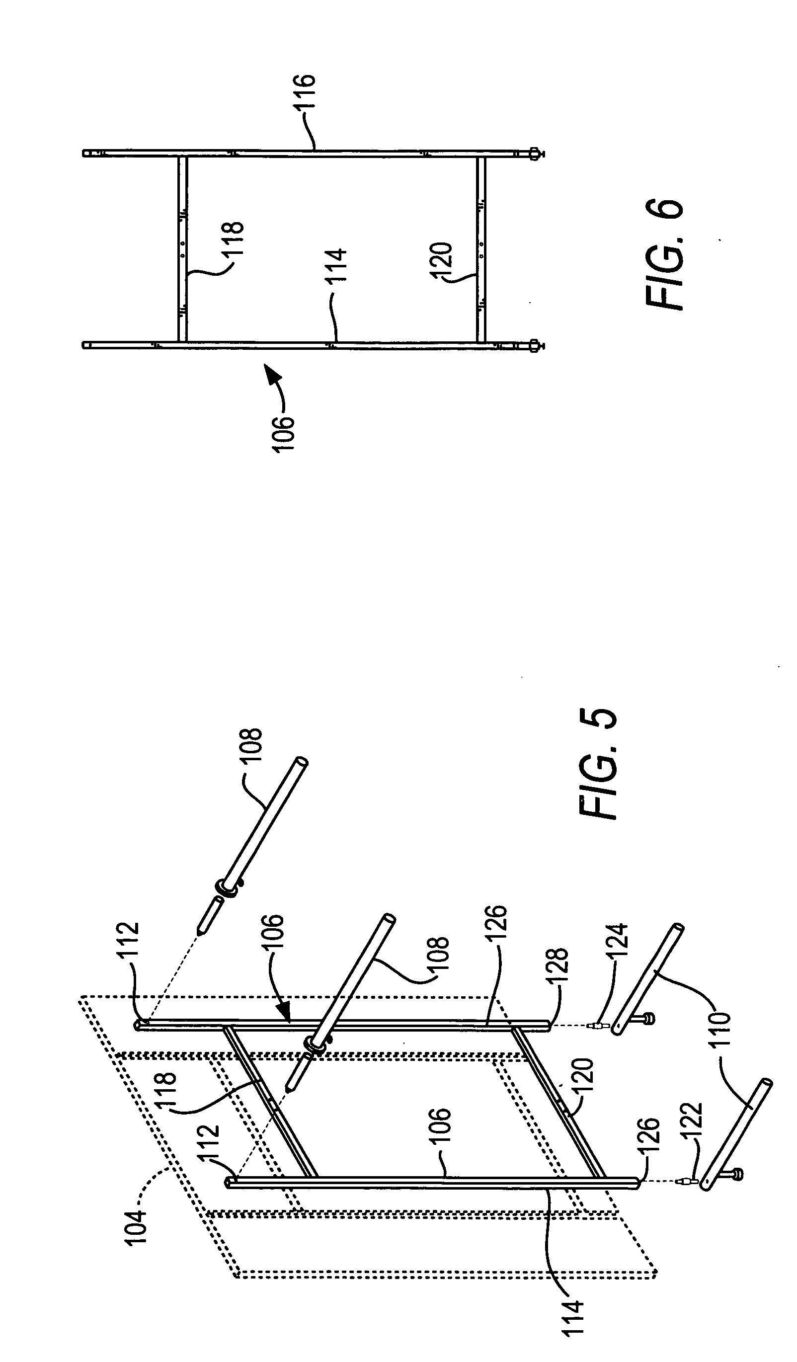
[0014] Referring now to the drawings in detail, and particularly to FIGS. 1-6, a presently preferred embodiment 100 of the floor display rack of the present invention is shown. As shown and preferred in FIG. 1, the floor display rack 100, which may be built to any desired hanging height, such as for example five feet, includes a pair of parallel decorative slab sides 102, 104, such as wooden slabs, a supporting steel crisscross framework 106 which is embedded or contained within each decorative slab 102, 104 (FIGS.>5-6), a pair of spaced apart horizontally extending steel hanging rods 108 structurally tied to the supporting framework 106 and the decorative slabs 102, and a horizontally extending steel base member 110 which is also structurally tied to the supporting framework 106. as shown and preferred, the hanging rods 108 structurally tie into horizontally extending mounting sockets 112 located in the supporting framework 106 in each of the decorative side slabs 102, 104, such as...


PUM


Abstract

A decorative retail merchandise floor display rack capable of bearing high capacity hanging loads includes a pair of spaced apart substantially parallel vertically extending slab side decorative panels, such as wooden panels, which each include a vertically extending structural steel criss-crossed supportg framework hidden inside which is capable of supporting vertical and horizontal loading on the display rack. The framework includes both horizontally extending and vertically extending mounting sockets for enabling the display rack components to be structurally tied together. A removable decorative covering for the slabs is provided which is also structurally tied into the display rack. Horizontally extending tubular steel hanging rods extend between the decorative panels for supporting hanging loads thereon, with steel rod like member extending through the horizontally extending tubular steel hanging rods and into the mounting sockets in the supporting framework where they are structurally tied in to the framework. A horizontally extending steel rod base member is spaced below the hanging rod members and extends substantially parallel thereto and is structurally tied to the supporting framework through the vertically extending mounting sockets for providing open box like supporting structure including the decorative slabs and the supporting framework to provide an integrally connected high capacity load bearing decorative retail merchandise floor display rack.

Description

CROSS REFERENCE TO RELATED APPLICATION [0001] This application is related to my commonly owned contemporaneously filed United States patent Application entitled “High Capacity Load Decorative Hanging Merchandise Display Rack”, which names Giusseppe Paventi as the sole inventor thereof, the contents of which are hereby incorporated by reference in their entirety. BACKGROUND OF THE INVENTION [0002] 1. Field of the Invention [0003] The present invention relates to the field of merchandise display racks and particularly to decorative floor display racks for retail merchandise which are both decorative and capable of bearing high capacity hanging loads. [0004] 2. Description of the Prior Art [0005] The art of display racks for hanging retail merchandise is practically as old as mankind itself. As such, retailers have always been faced with the dual problem of displaying merchandise in an aesthetic manner to attract the buyer as well as providing the best possible loading characteristics ...

Claims


Application Information

Patent Timeline
Patent Type & Authority Applications(United States)
IPC IPC(8): A47F5/00A47F5/08
CPCA47F5/0838A47F5/00
Inventor PAVENTI, GIUSEPPE
Owner JP METAL AMERICA
Why Eureka
Try Eureka