Methods and apparatus for using imaging information to improve scanning accuracy in bar code scanners

a bar code scanner and imaging information technology, applied in the field of bar code scanners and bar code scanning, can solve the problems of missed scans, impaired scanning of some objects, and failure of bar code scanning,

Inactive Publication Date: 2005-05-19
NCR CORP
View PDF8 Cites 34 Cited by
  • Summary
  • Abstract
  • Description
  • Claims
  • Application Information

AI Technical Summary

Benefits of technology

[0007] The bar code module may suitably provide timing information to the time and space module. The timing information indicates when a bar code is detected, and this timing information can be used by the time and space module to estimate imaging information about the object or objects in the field of view of the scanner when the bar code is detected. This information may include the size, shape, position and direction of travel of the object or objects. The time and space module transfers the imaging information to the bar code module, which then uses the imaging information to assist in decoding the bar code or bar codes. For example, the imaging information may indicate that there are two objects each of which has its own bar code label within the field of view of th

Problems solved by technology

At times during the scanning of a succession of objects, the scanning of some of the objects may be impaired for any of a number of reasons.
For example, missed scans may occur due to a failure of an operator to bring the bar code into the field of view of the scanner.
A sca

Method used


Image

  • Methods and apparatus for using imaging information to improve scanning accuracy in bar code scanners
  • Methods and apparatus for using imaging information to improve scanning accuracy in bar code scanners
  • Methods and apparatus for using imaging information to improve scanning accuracy in bar code scanners

Examples


Embodiment Construction

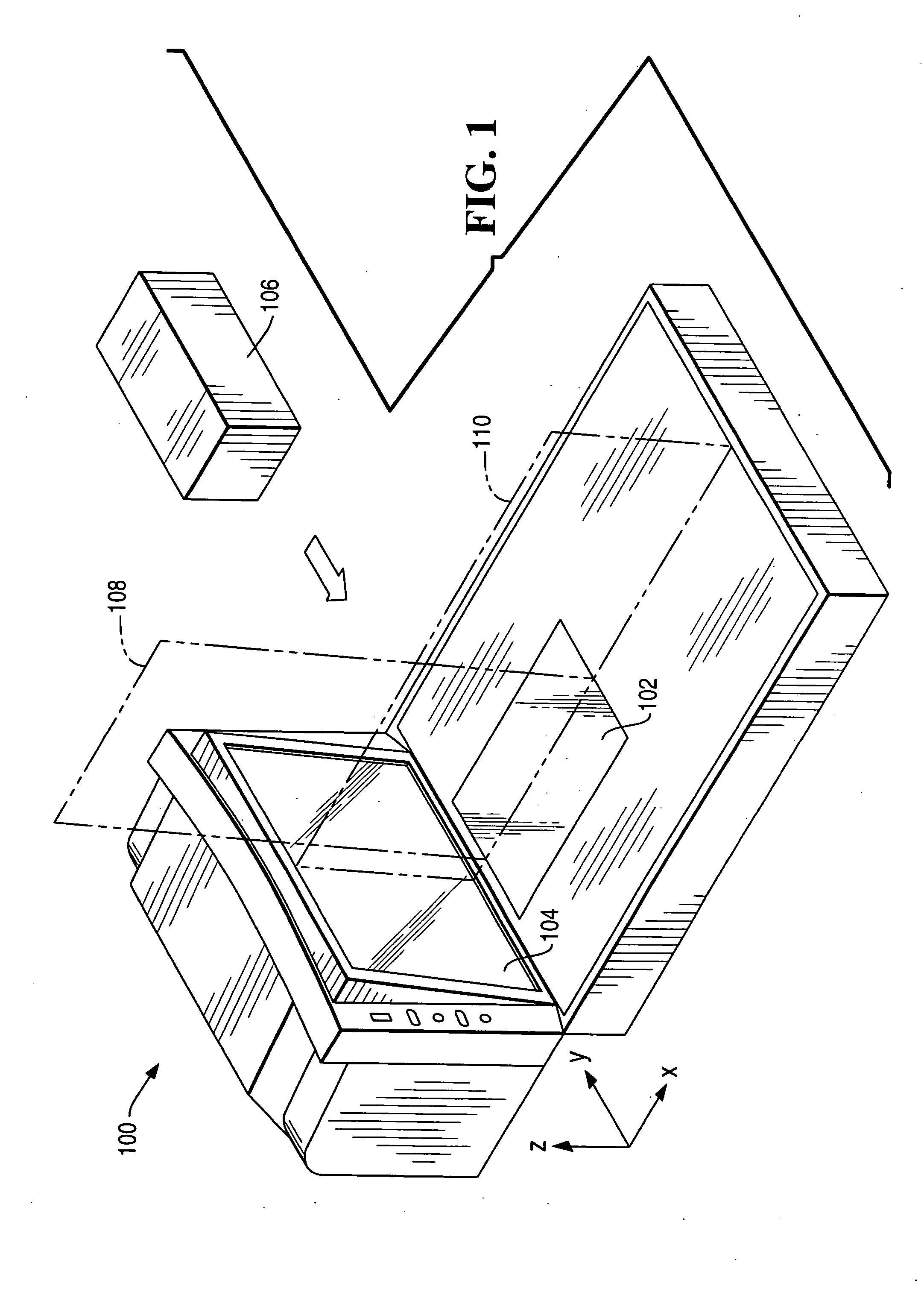
[0015]FIG. 1 illustrates a scanner 100 having a horizontal scan window 102 and a vertical scan window 104, according to the present invention. The scanner 100 generates a scanner signal based on light reflected from an object passing within the field of view of one or both of the windows 102 and 104. In FIG. 1, the example of a box 106 being passed within range of the scan windows 102 and 104 is illustrated. In this illustration, the box 106 passes through a first scan plane 108 emitted from the horizontal scan window 102 and a second scan plane 110 emitted from the vertical scan window 104. Each of the scan planes 108 and 110 is produced by the tracing of a scan beam along a path determined by the rotation of a spinner within the scanner 100. As the box 106 passes within the field of view of the scanner windows 102 and 104, the box 106 intersects the scan planes 108 and 110, the box 106 simultaneously intersects both of the scan planes 102 and 104. During the time that the box 106 ...


PUM


Abstract

Techniques for using imaging information computed from examining a scanner signal are described. When one or more objects passes within a field of view of a scanner, scan patterns emerging from one or more scanner windows and reflected from the objects back into the scanner windows produce one or more scanner signals. The scanner signals are processed to obtain beam position and beam length information to improve the accuracy of bar code decoding and to compute imaging information for objects within the field of view of the scanner. The imaging information for the objects is compared with bar code information for the objects. The expected number, size and shapes of objects indicated by the bar code information is compared with the actual number, size and shapes of objects in order to determine if valid scans occurred or if missed, double or otherwise erroneous scans occurred.

Description

FIELD OF THE INVENTION [0001] The present invention relates generally to improvements to bar code scanners and bar code scanning. More particularly, the invention relates to advantageous techniques for interpreting a scanner signal to obtain information about the size, shape, position and motion of an object in the scan field of the scanner and using this information to improve the accuracy of decoding of a bar code on the object. BACKGROUND OF THE INVENTION [0002] Bar code scanners are used in a wide variety of applications, such as retailing, inventory control, customer identification and many other applications. Many bar code scanners are adapted to scan a bar code located on an object, when the object is placed within the field of view of the scanner. Many such scanners produce complex scan patterns in order to maximize coverage of an object, so that a bar code located on an object will produce a readable reflection, even if the bar code is located on a relatively obscure area o...

Claims


Application Information

Patent Timeline
IPC IPC(8): G06K7/10
CPCG06K7/1096G06K7/10792
Inventor MERGENTHALER, BARRY M.DETWILER, PAUL OLIVERBURKEY, JOHN KENNETHGU, YEMING
Owner NCR CORP
Why Eureka
Try Eureka