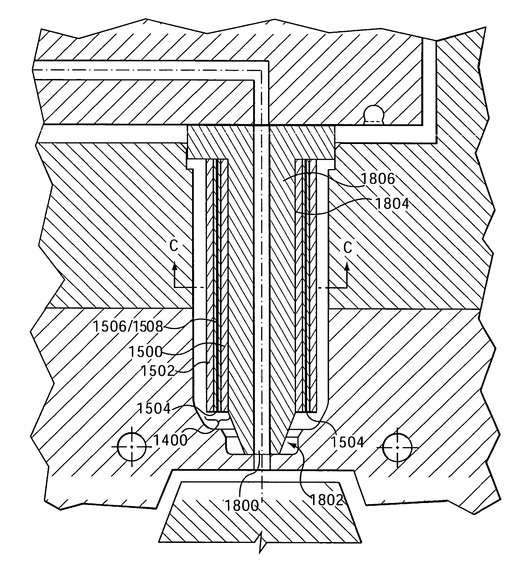
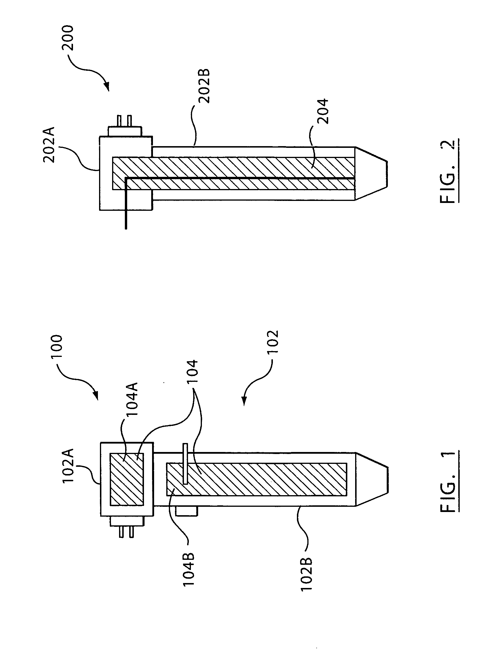
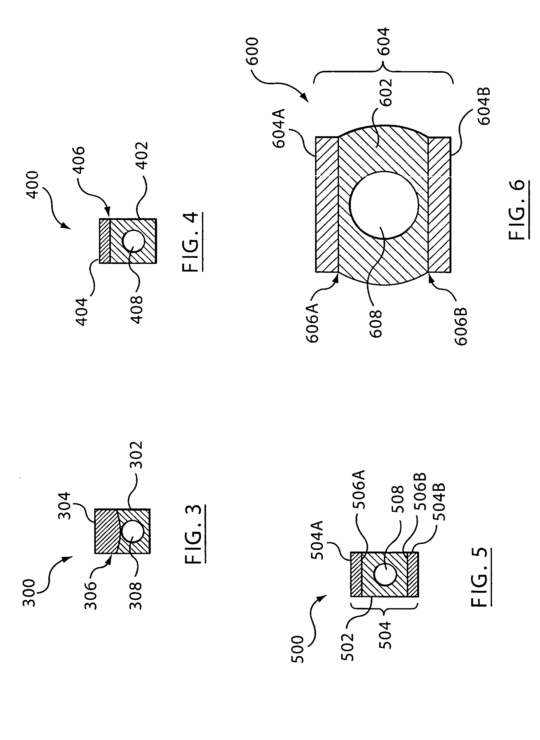
Injection nozzle with a removable heater device having one or more heating elements

a heater device and injection nozzle technology, which is applied in the field of heating and heaters for injection molding nozzles, can solve the problems of providing non-uniform heat profiles along the nozzles shown in the '387 and '795 patents, affecting the and affecting the efficiency of injection molding, etc., to achieve compact size of the film heater device, easy visual inspection, and perfect repeatability of patterned layers

Active Publication Date: 2005-05-19
MOLD MASTERS 2007
View PDF37 Cites 18 Cited by
  • Summary
  • Abstract
  • Description
  • Claims
  • Application Information

AI Technical Summary

Benefits of technology

[0022] Using film heating elements can provide for mass production of the film heating elements with substantially perfect repeatability of patterned l

Problems solved by technology

This makes the nozzles shown in the '387 and '795 patents somewhat bulky and impractical for inside gating and small pitch applications.
Similar to the DE '374 document, the '322 PPA increases the size of the nozzle along one direction making it impractical for internal gating of small parts.
These heating devices also provide a non-uniform heat profile along the nozzle melt channel.
Nevertheless making layered resistive heating elements on a cylindrical or 3D surface is on one hand a time consuming method and on the other hand is a method that cannot be applied to manufacture simultaneously a large number of heating elements in batches that deliver heaters having the same geometrical and functional characteristics.
However, the '188 PPA requires the heater device to be permanently coupled to the flat nozzle,

Method used


Image

  • Injection nozzle with a removable heater device having one or more heating elements
  • Injection nozzle with a removable heater device having one or more heating elements
  • Injection nozzle with a removable heater device having one or more heating elements

Examples


Embodiment Construction

Overview

[0041] While specific configurations and arrangements are discussed, it should be understood that this is done for illustrative purposes only. A person skilled in the pertinent art will recognize that other configurations and arrangements can be used without departing from the spirit and scope of the present invention. It will be apparent to a person skilled in the pertinent art that this invention can also be employed in a variety of other applications.

[0042] Embodiments of the present invention provide an injection molding system and an injection molding method where one or more planar heater devices (e.g., rigid, flexible) comprise thin or thick film deposited resistive layers, etc. These flat-planar nozzle heaters including film deposited layers are coupled, secured, or releaseably secured (hereinafter, all are referred to as “coupled”) to one or more sides of one or more nozzles having at least one flat-planar, or quasi flat-planar nozzle surface). The coupling of th...


PUM

PropertyMeasurementUnit
Temperatureaaaaaaaaaa
Sizeaaaaaaaaaa
Electrical conductoraaaaaaaaaa

Abstract

An injection molding system and injection molding method for making molded parts that include one or more planar heaters having a thin or a thick film resistive heater element coupled, secured, or releaseably secured to one or more sides of each of the one or more injection molding nozzles. The releasably secure coupling allows heater device to be visually inspected, tested, removed, and/or replaced. The planar heater device can have a support device patterned with a film electrical resistive path. The electrical resistive path can include any pitch or number of electrical resistance lines, such that a longitudinal uniform heat profile is generated along a melt flow channel of the one or more injection molding nozzles when the nozzles are in use. In some examples, the planar heater has more than one film resistive heater element that can be coupled to one or each side of a nozzle, with dielectric material interposed between the planar film resistive heater elements. This can allow for additional or alternative heating in various applications.

Description

CROSS-REFERENCE TO RELATED APPLICATIONS [0001] This application is a continuation-in-part of U.S. application Ser. No. 10 / 701,493, filed Nov. 6, 2003, entitled “Injection Nozzle with Planar Heater,” which claims benefit under 35 U.S.C. § 119(e) to U.S. Provisional Application No. 60 / 424,004, filed Nov. 6, 2002, entitled “Injection Nozzle With Planar Heater,” which are incorporated by reference herein in their entireties. [0002] This application also claims benefit under 35 U.S.C. 119(e) to U.S. Provisional Patent Application No. 60 / 518,744, filed Nov. 12, 2003, entitled “Injection Nozzle With A Removable Film Heater Device Having Multiple Film Heating Elements,” which is incorporated by reference herein in its entirety.BACKGROUND OF THE INVENTION [0003] 1. Field of the Invention [0004] The present invention is related to heating and heaters for injection molding nozzles, more particularly for injection nozzles used in injection molding applications. [0005] 2. Background Art [0006] N...

Claims


Application Information

Patent Timeline
IPC IPC(8): B29C45/27
CPCB29C45/2737B29C2045/2788B29C2045/2754B29C2045/275
Inventor OLARU, GEORGE
Owner MOLD MASTERS 2007
Why Eureka
Try Eureka