Method and apparatus for implementing automated electronic package transmission line characteristic impedance verification

a technology of electronic package transmission line and characteristic impedance, which is applied in the direction of resistance/reactance/impedence, line-transmission details, instruments, etc., can solve the problems of complex and expensive electronic test instruments that are required to generate and measure input excitation waveforms, inconvenient production manufacturing environment, and inability to analyze the near-end waveform of the transmission lin

Inactive Publication Date: 2005-05-19
IBM CORP
View PDF4 Cites 9 Cited by
  • Summary
  • Abstract
  • Description
  • Claims
  • Application Information

AI Technical Summary

Benefits of technology

[0012] A principal object of the present invention is to provide a method and apparatus for implementing automated electronic package transmission line characteristic impedance verification. Other important objects of the present invention are to provide such method and apparatus for implementing automated electronic package transmission line characteristic impedance verification substantially without negative effect and that overcome many of the disadvantages of prior art arrangements.

Problems solved by technology

The disadvantages of this approach include the following: (A) Complex and expensive electronic test instrumentation is required to generate and measure the input excitation waveform.
(B) Analysis of the transmission line's near-end waveform is relatively complex and requires subjective analytic interpretation, and thus is often not convenient for a production manufacturing environment.
(C) The time-domain input signal has multiple frequency components, leading to an inherent ambiguity in the frequency at which the characteristic impedance measurement was performed.

Method used


Image

  • Method and apparatus for implementing automated electronic package transmission line characteristic impedance verification
  • Method and apparatus for implementing automated electronic package transmission line characteristic impedance verification
  • Method and apparatus for implementing automated electronic package transmission line characteristic impedance verification

Examples


Embodiment Construction

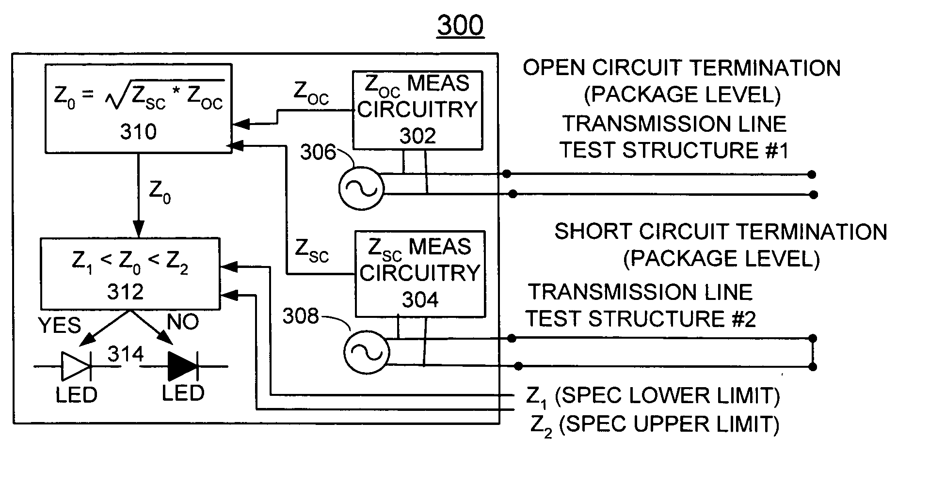
[0019] In accordance with features of the preferred embodiment, a method is provided for verifying an electronic- package's characteristic impedance through the utilization of a single electronic integrated circuit device, thereby making its measurement very repeatable and easily interpretable in a production manufacturing environment.

[0020] Having reference now to the drawings, two embodiments of the invention are provided and illustrated in FIGS. 3 and 4. In FIG. 3, there is shown apparatus for implementing automated electronic package transmission line characteristic impedance verification generally designated by the reference character 300 in accordance with one preferred embodiment. In FIG. 4, there is shown apparatus for implementing automated electronic package transmission line characteristic impedance verification generally designated by the reference character 400 in accordance with another preferred embodiment. In both embodiments 300, 400, one or more test traces are bu...


PUM


Abstract

A method and apparatus are provided for implementing automated electronic package transmission line characteristic impedance verification. A sinusoidal voltage source is coupled to a transmission line test structure for generating a selected frequency. Impedance measuring circuitry is coupled to the transmission line test structure for measuring an input impedance with an open-circuit termination and a short-circuit termination. Characteristic impedance calculation circuitry is coupled to the impedance measuring circuitry receiving the input impedance measured values for the open-circuit termination and the short-circuit termination for calculating characteristic impedance. Logic circuitry is coupled to the characteristic impedance calculation circuitry for comparing the calculated characteristic impedance with threshold values for verifying acceptable electronic package transmission line characteristic impedance.

Description

FIELD OF THE INVENTION [0001] The present invention relates to a method and apparatus for implementing automated electronic package transmission line characteristic impedance verification. DESCRIPTION OF THE RELATED ART [0002] For the design of transmission lines in electronic packages, one of the most critical parameters to control is the characteristic impedance ZO. The characteristic impedance of transmission lines in electronic packages with high interconnect densities is most commonly measured using time-domain techniques such as time-domain reflectometry (TDR). TDR techniques assume a particular time-domain input excitation waveform, namely, a fast edge transition with a known rise time. [0003]FIG. 1 illustrates the setup for such TDR characteristic impedance measurement techniques. The characteristic impedance is then calculated by analyzing the waveform at the near-end of the transmission line being tested. [0004] The disadvantages of this approach include the following: [00...

Claims


Application Information

Patent Timeline
Patent Type & Authority Applications(United States)
IPC IPC(8): G01R27/04G01R27/28G01R31/02H04B3/46
CPCG01R27/04
Inventor BARTLEY, GERALD KEITHDAHLEN, PAUL ERICGERMANN, PHILIP RAYMONDMAKI, ANDREW B.MAXSON, MARK OWEN
Owner IBM CORP
Why Eureka
Try Eureka