Eureka AIR delivers breakthrough ideas for toughest innovation challenges, trusted by R&D personnel around the world.

Apparatus and method for receiving RF signal free of 1/f noise in radio communication system

Inactive Publication Date: 2007-05-29
SAMSUNG ELECTRONICS CO LTD
View PDF10 Cites 3 Cited by
  • Summary
  • Abstract
  • Description
  • Claims
  • Application Information

AI Technical Summary

Benefits of technology

[0007]An apparatus and method for receiving RF signals without ef

Problems solved by technology

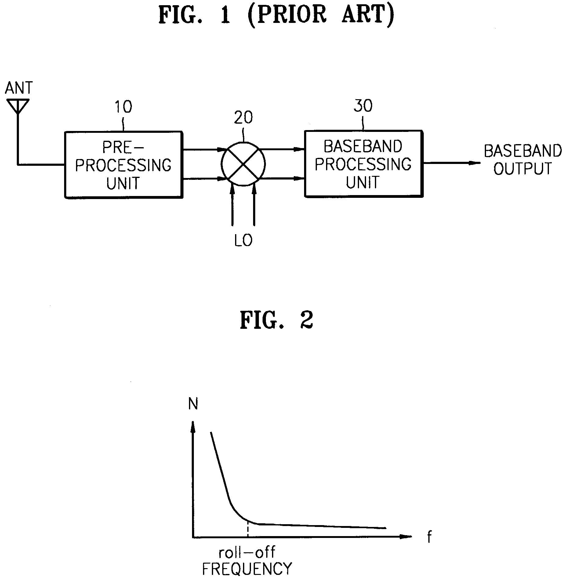
Particularly, in the case of implementing the direct conversion receiver with CMOS technology, a frequency roll-off as shown in FIG. 2 increases to an order of a few mega-hertz (MHz) and an effect due to 1 / f noise becomes significant.
Further, due to such 1 / f noise, the sensitivity of the receiver is considerably degraded.
Such sensitivity degradation of the receiver causes more serious problems in a narrow band system such as a GSM system and, therefore, conventional narrow-band direct-conversion receivers have not employed CMOS technology.

Method used


Image

  • Apparatus and method for receiving RF signal free of 1/f noise in radio communication system
  • Apparatus and method for receiving RF signal free of 1/f noise in radio communication system
  • Apparatus and method for receiving RF signal free of 1/f noise in radio communication system

Examples


Embodiment Construction

[0018]A preferred embodiment of an apparatus and method for receiving radio frequency (RF) signals in a RF communication system according to embodiments of the present invention will be described herein below.

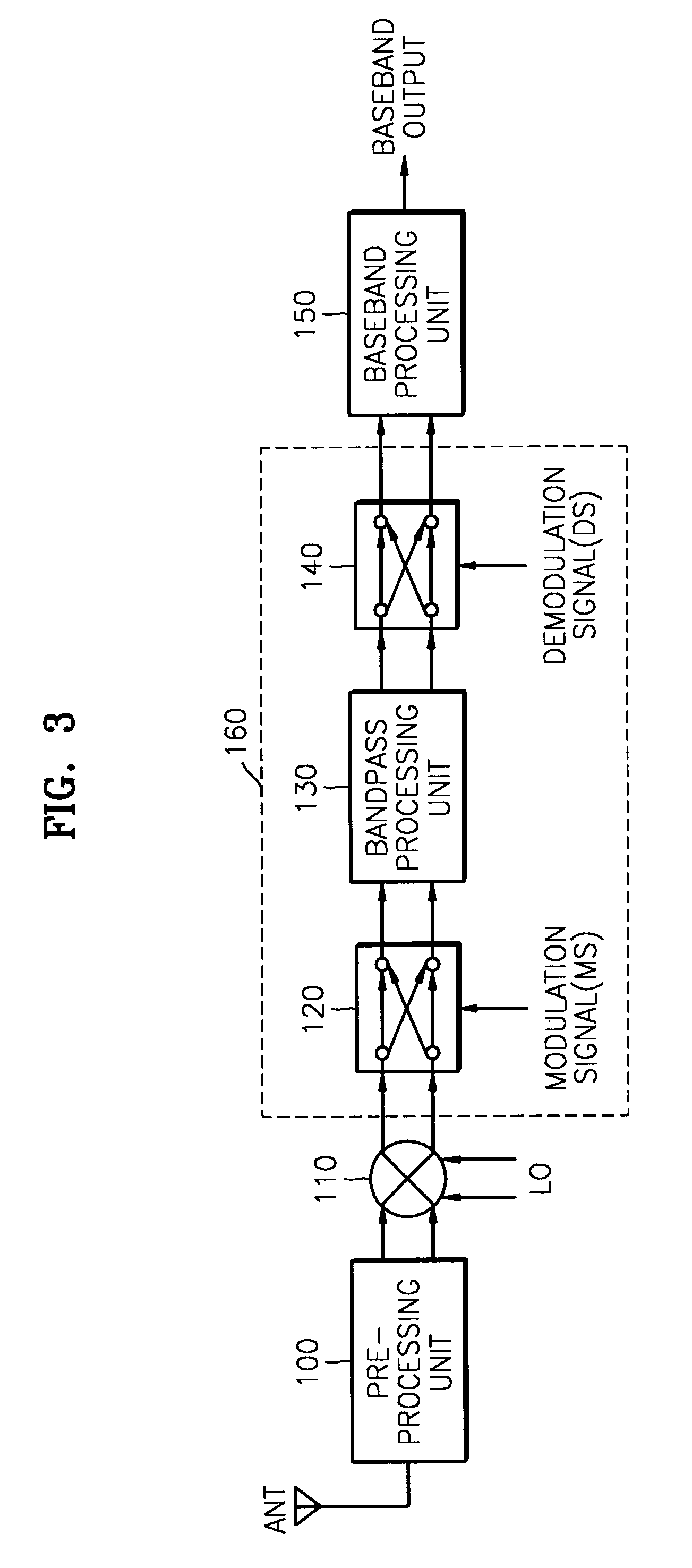
[0019]FIG. 3 is a schematic block diagram of an embodiment of a RF receiver according to the present invention. Referring to FIG. 3, the RF receiver according to an embodiment of the present invention comprises a pre-processing unit 100, a mixer 110, a noise-free-signal amplifying unit 160, and a baseband processing unit 150.

[0020]The pre-processing unit 100 bandpass-filters a received RF signal with a predetermined bandwidth fband so as to extract a desired RF signal. Additionally, the pre-processing unit 100 amplifies and outputs the filtered RF signal as a RF input signal. Typically, the pre-processing unit 100 includes a RF switch, a pre-selection bandpass filter, and a low noise amplifier (LNA) (not shown).

[0021]The mixer 110 lowers a frequency of the RF input signal provi...


PUM


Abstract

An apparatus and method for receiving RF signals in a RF communication system are provided. The apparatus for receiving RF signals comprises a pre-processing unit for bandpass-filtering a signal received through an external antenna with a predetermined bandwidth and extracting a RF input signal having a desired frequency; a mixing unit for mixing the RF input signal provided from the pre-processing unit with a local oscillation signal having the same frequency as the RF input signal and generating a desired baseband signal; a noise-free-signal amplifying unit for shifting the desired baseband signal to a band that is free of effects due to 1 / f noise, amplifying the shifted baseband signal, and re-shifting the amplified signal to the baseband; and a baseband processing unit for selecting a desired channel signal from the amplified baseband signal to be provided from the noise-free-signal amplifying unit and amplifying the selected signal.

Description

BACKGROUND OF THE INVENTION[0001]This application claims priority to Korean Patent Application No. 2002-58119, filed Sep. 25, 2002, in the Korean Intellectual Property Office.[0002]1. Field of the Invention[0003]The present invention relates generally to a radio communication system and, more particularly, to an apparatus and method for receiving radio frequency (RF) signals by which sensitivity degradation due to 1 / f noise can be minimized.[0004]2. Description of the Related Art[0005]In order to satisfy continuous demands on multi-functional, high-performance radio frequency (RF) communication services and to facilitate highly integrated, smaller sized and more energy efficient communication systems, a direct conversion type receiver as shown in FIG. 1 has been widely used as a RF receiver in recent RF communication systems. The direct conversion receiver includes a pre-processing unit 10 for band-pass filtering an input RF signal received through an external antenna ANT, a mixer 2...

Claims


Application Information

Patent Timeline
IPC IPC(8): H03K9/00H04B1/10H03D7/16
CPCH03D7/163H04B1/10
Inventor KIM, JAE-WANHWANG, IN-CHULSEO, HAE-MOONKIM, YOUNG-JIN
Owner SAMSUNG ELECTRONICS CO LTD
Why Eureka
Eureka Blog
Learn More