Vehicle light and method for manufacturing the same

a technology for vehicles and light sources, applied in the manufacture of electrode systems, electric discharge tubes/lamps, light and heating apparatus, etc., can solve the problems of difficult to determine whether such a transparent anti-fog coating has been applied or not, and it is difficult to determine whether such a transparent anti-fog coating has been applied by visual inspection of such a boundary line, etc., to achieve smoothing of irregularities of texturing processing surfaces.

Active Publication Date: 2009-05-14
STANLEY ELECTRIC CO LTD
View PDF5 Cites 5 Cited by
  • Summary
  • Abstract
  • Description
  • Claims
  • Application Information

AI Technical Summary

Benefits of technology

[0024]When part of the first area has not been applied with a coating for surface treatment, one can visually inspect the texturing processed surface where no coating is provided, with ease. Accordingly, even when the application process has been finished properly or not, any defective product which has not been properly applied with a coating can be detected based on the state of the first area.
[0025]Furthermore, when the first area is applied with a coating for surface treatment, the irregularities of the texturing processed surface can be smoothened. As a result, the optical characteristics including the transparency, the reflectance and the like of that portion may be changed. When transmittance or reflectance of the portion of the first area that is applied with the coating for surface treatment is optically determined, the determination of whether the outer lens is properly coated or not can be achieved by the difference between the detected values before and after the application process.
[0026]In the above configuration, the outer lens can include the second area which is adjacent to the first area and is not subjected to the texturing process, and part of the first area and the second area can be applied with the coating for surface treatment. In this case, the first area having been subjected to texturing process and the second area not having been subjected to texturing process are compared with each other with regard to the application of the coating for surface treatment. Accordingly, the determination of whether the coating has been present or not can be more easily achieved.
[0027]The bonding area where the outer lens and the housing are bonded to each other may include at least part of, or all of, the first area and the second area of the outer lens. When both the entire first area and the entire second area are included in the bonding area, the first and second areas are positioned near the bonding area of the housing when assembled. Accordingly, when light from the light source of the vehicle light is reflected by the reflecting surface and passes through the outer lens, the light does not pass through the first area and / or the second area. This means that the illumination light can be projected with a predetermined light distribution pattern without any effect by the first area and / or the second area. Further, if the bonding area and its surroundings do not affect the light distribution pattern, part of or all of the first area and / or the second area can be located outside the bonding area.
[0028]As described above, in accordance with the presently disclosed subject matter, a vehicle light can be provided with a simple configuration by which determination as to whether a coating such as an anti-fog coating, a hard coating for surface treatment, and the like has been applied or not can be easily accomplished. Furthermore, according to the presently disclosed subject matter, a method for manufacturing such a vehicle light can be provided.

Problems solved by technology

The moisture that enters can adhere to the inner surface of the outer lens resulting in mist on the lens.
Accordingly, when a completed product including the outer lens is observed, it is difficult to determine whether such a transparent anti-fog coating has been applied or not.
However, it is not easy to determine whether the anti-fog coating has been applied by visual inspection of such a boundary line.
Furthermore, there is no other fallback determination method.
If a partially finished product that does not include the anti-fog coating comes to be mixed into the final assembly process of the vehicle lamp after the anti-fog coating process, the resulting finished products contain defective uncoated products which cannot be clearly distinguished from the nondefective coated products.

Method used


Image

  • Vehicle light and method for manufacturing the same
  • Vehicle light and method for manufacturing the same
  • Vehicle light and method for manufacturing the same

Examples


Embodiment Construction

[0035]A description will now be made below to exemplary embodiments of vehicle lights made in accordance with principles of the presently disclosed subject matter with reference to the accompanying drawings.

[0036]FIG. 1 shows the configuration of a vehicle light in accordance with a first exemplary embodiment of the presently disclosed subject matter.

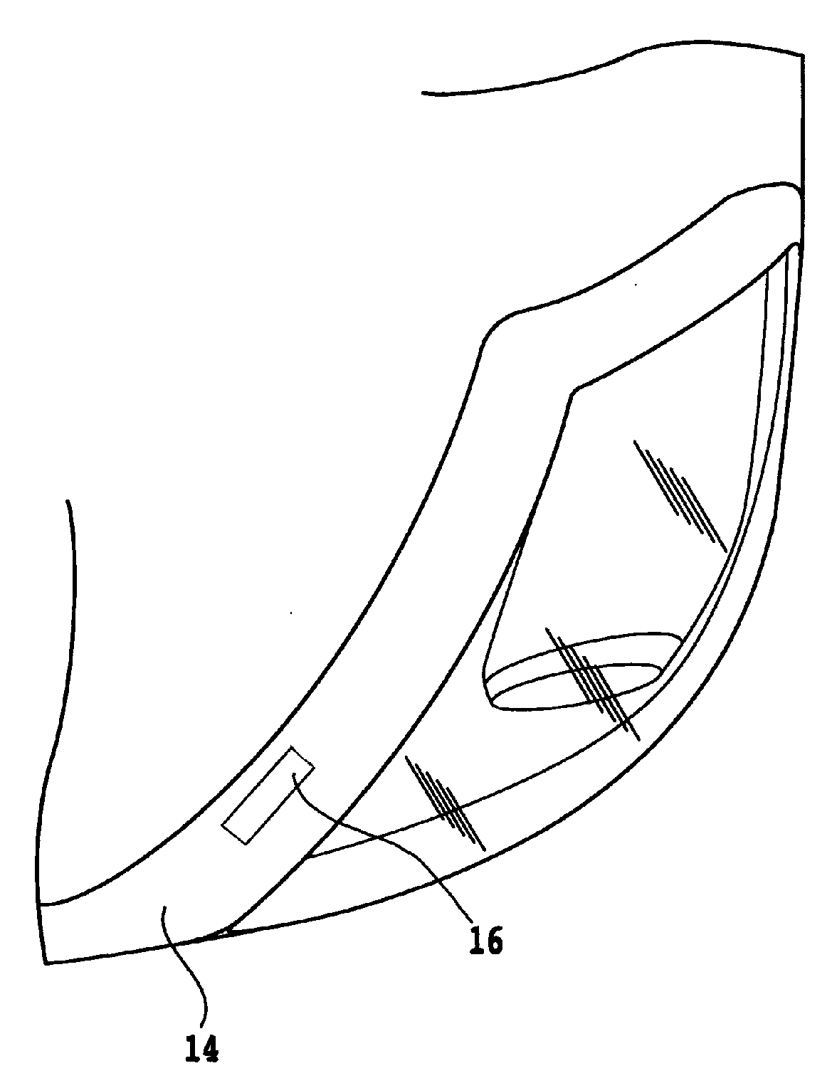
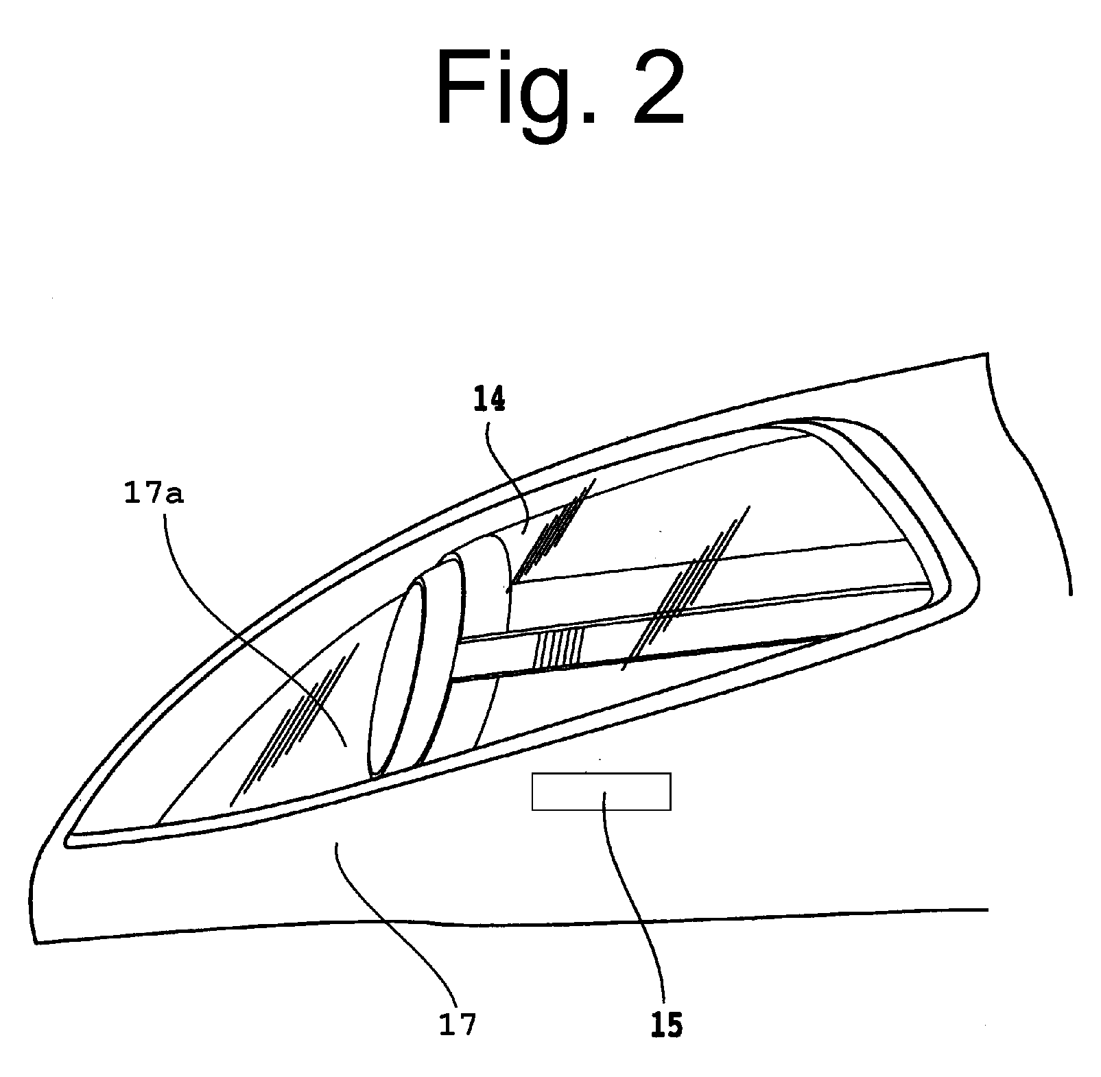
[0037]In FIG. 1, the vehicle light 10 can be configured as a vehicle headlight. The vehicle light 10 can include: a bulb 11 serving as a light source; a reflecting surface 12 configured to reflect light from the bulb 11 to the front direction of the vehicle (or in the illumination direction for the vehicle light); a housing 13 configured to hermetically house the bulb 11 and the reflecting surface 12; an extension 17 covering the area near the open ends of the reflecting surface 12 and the housing 13 so that the housing 13 is prevented from being directly observed through the outer lens 14 when the vehicle light 10 is seen from the fron...


PUM


Abstract

A vehicle light can have a simple configuration for easily determining whether or not a coating, such as an anti-fog coating and a hard coating, has been applied to a lens. A manufacturing method of such a vehicle light is also disclosed. The vehicle light can include a housing opened in an illumination direction, a light source disposed within the housing, a reflecting surface disposed within the housing and configured to reflect light from the light source to the illumination direction, and an outer lens disposed so as to hermetically close the front open end of the housing. The outer lens can have an inner surface and an outer surface, at least one of which including a coating for surface treatment. The outer lens can further have a first area which is subjected to a texturing process on the inner surface and/or the outer surface, with at least part of the first area including the coating for surface treatment.

Description

[0001]This application claims the priority benefit under 35 U.S.C. § 119 of Japanese Patent Application No. 2007-254541 filed on Sep. 28, 2007, which is hereby incorporated in its entirety by reference.BACKGROUND[0002]1. Technical Field[0003]The presently disclosed subject matter relates to a vehicle light such as a vehicle headlight, an auxiliary headlight, a rear combination lamp, and the like, having an outer lens. The presently disclosed subject matter also relates to a method for manufacturing the same.[0004]2. Description of the Related Art[0005]In a conventional vehicle light including an outer lens, moisture may enter the inside of the light during use. The moisture that enters can adhere to the inner surface of the outer lens resulting in mist on the lens. In order to prevent this, the inner surface of the outer lens may include an anti-fog coating applied thereto.[0006]In this case, such an anti-fog coating should be transparent. Accordingly, when a completed product inclu...

Claims


Application Information

Patent Timeline
Patent Type & Authority Applications(United States)
IPC IPC(8): F21V7/00F23Q23/08H01J9/00F21Y101/00
CPCF21S48/10F21V3/04F21S48/20F21S41/28F21S43/26F21S45/10F21S45/50
Inventor ISHIZU, MOTOYASUYOSHIKAWA, KAZUO
Owner STANLEY ELECTRIC CO LTD
Why Eureka
Try Eureka