Position detecting system and position detecting apparatus

a technology of position indicator and position indicator, which is applied in the field of position indicator apparatus, can solve the problems of reducing difficult difficulty in excitation of position indicator, so as to improve the excitation efficiency of position indicator

Inactive Publication Date: 2005-05-19
WACOM CO LTD
View PDF14 Cites 19 Cited by
  • Summary
  • Abstract
  • Description
  • Claims
  • Application Information

AI Technical Summary

Benefits of technology

[0019] According to the present invention, the excitation efficiency of the position indicator can be improved in the entire area of the sensor unit, including the end portion thereof, in the simply-configured position detecting system and position detecting apparatus that utilizes electromagnetic coupling.
[0020] Also, according to the present invention, the effect of the metallic bezel provided at the periphery of the display unit can be alleviated in the simply-configured position detecting system and position detecting apparatus that utilizes electromagnetic coupling.

Problems solved by technology

However, when the position indicator is positioned near a plane provided with the transmission coil 801 and the sensor coils 802 (sensor plane) but far from the transmission coil 801, the position indicator is difficult to excite.
Therefore, a magnetic flux output from the transmission coil 801 flows into the shield member, and thus the position indicator is difficult to excite.
Accordingly, a magnetic flux in the opposite direction to that of the excitation for the position indicator is generated, which causes an undesirable decrease in the excitation efficiency.

Method used


Image

  • Position detecting system and position detecting apparatus
  • Position detecting system and position detecting apparatus
  • Position detecting system and position detecting apparatus

Examples


second embodiment

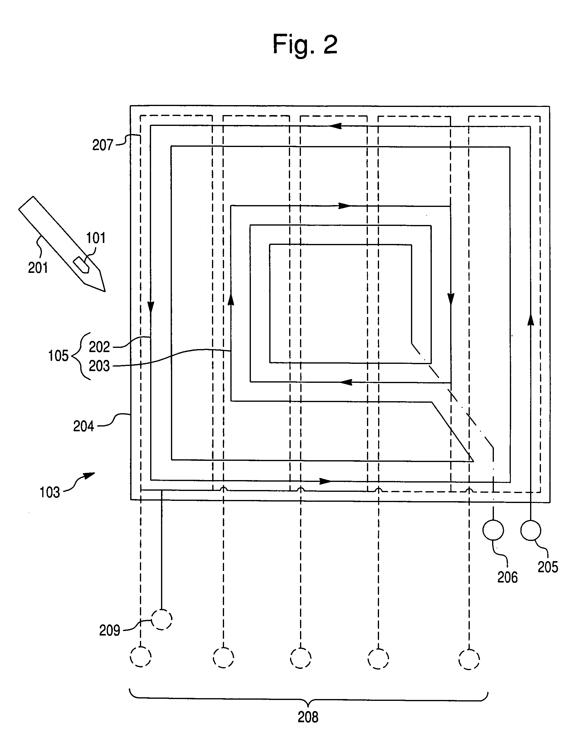
[0040] Although the details will be described in a second embodiment, the positional relationship and the turn ratio of the external transmission coil 202 and the internal transmission coil 203 are determined so that an exciting current generated by driving the external transmission coil 202 and the internal transmission coil 203 does not flow through a metallic bezel, which is provided at the periphery of a display device. In FIG. 2, the number of turns of the internal transmission coil 203 is larger than that of the external transmission coil 202.

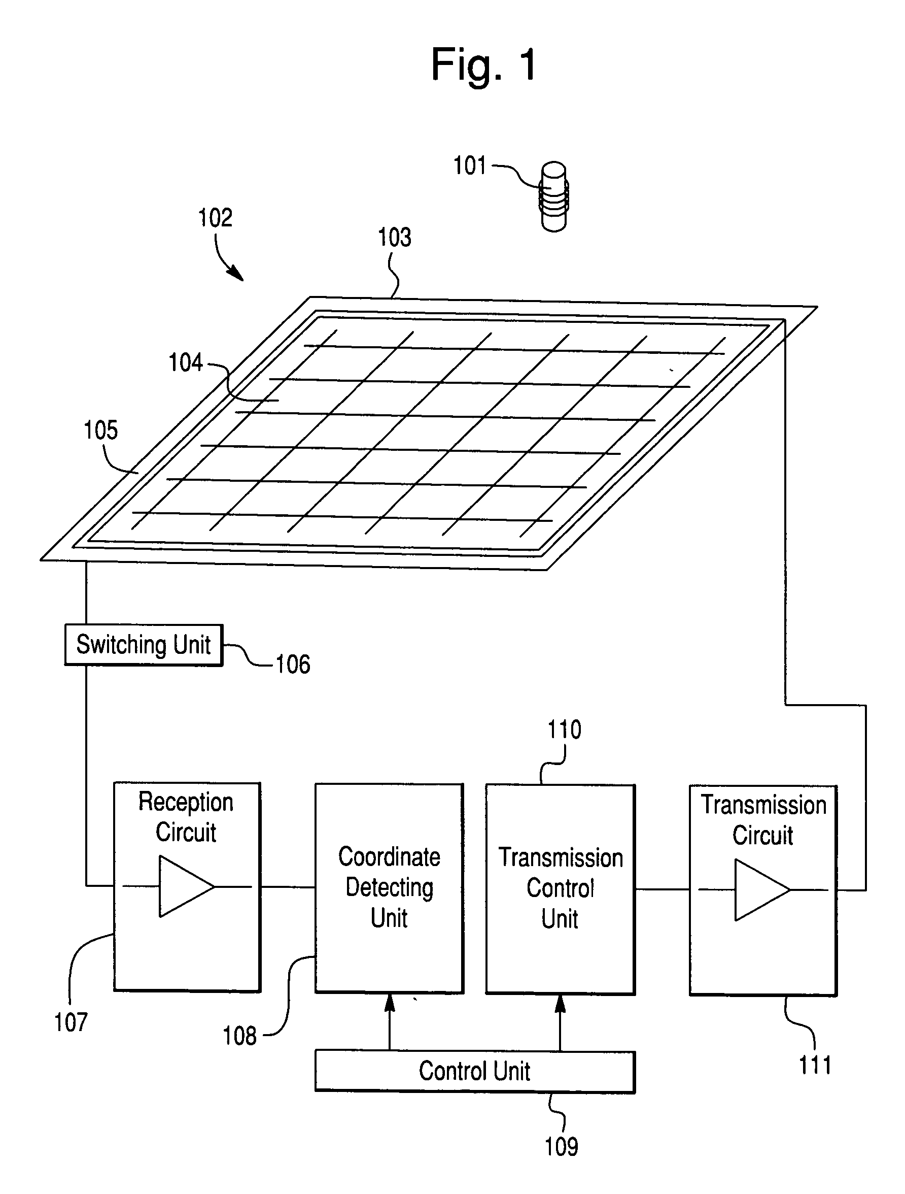
[0041] Position detecting signals are supplied between an input terminal 205 and a common terminal 206 of the transmission coils 202 and 203 from the transmission circuit 111. Accordingly, each of the transmission coils 202, 203 is driven so as to transmit the position detecting signals to the position indicator 101. The switching unit 106 sequentially selects the sensor coils in the sensor coil unit 104 and outputs position indicating si...

first embodiment

[0044]FIG. 3 is a timing chart showing the operation of the position detecting system according to the In this embodiment, the position of the position indicator 101 is detected by scanning the X-direction sensor coils and then scanning the Y-direction sensor coils.

[0045]FIG. 4 illustrates the operation of the position detecting system according to this embodiment. Hereinafter, the operation of the position detecting system and the position detecting apparatus according to the first embodiment will be described in detail with reference to FIGS. 1 to 4.

[0046] First, the entire operation of detecting the position of the position indicator 101 by using the position detecting system will be described.

[0047] The transmission control unit 110 outputs a position-detecting signal under the control of the control unit 109. The transmission circuit 111 amplifies the position-detecting signal and outputs the signal to the transmission coil unit 105 under the control of the control unit 109....


PUM


Abstract

A position detecting apparatus transmits position detecting signals from internal and external transmission coils, which are electrically connected to each other and are wound in opposite directions. The signals are transmitted to a position indicator that is housed within a pen-shaped input member. Since the internal and external transmission coils are wound in opposite directions, the position indicator can be efficiently excited in the entire area of a sensor unit including the end portion thereof. The position indicator receives the position detecting signals and transmits position indicating signals indicating a position. Sensor coils receive the signals from the position indicator. The position detecting apparatus detects the position of the position indicator based on the signals detected by the sensor coils.

Description

CROSS-REFERENCE TO RELATED APPLICATIONS AND CLAIM TO PRIORITY [0001] This application claims priority under 35 U.S.C. §119 to application number 2003-333123, filed Sep. 25, 2003, in Japan, the disclosure of which is incorporated herein by reference. FIELD OF THE INVENTION [0002] The present invention relates to a position detecting apparatus which may be used as an input device or the like for a computer aided design (CAD) system, a computer, a mobile phone, a personal handyphone system (PHS), a personal digital assistant (PDA), etc. The apparatus detects a position indicated by a position indicator by using electromagnetic coupling. The present invention also relates to a position detecting system that incorporates the position indicator and the position detecting apparatus described above. BACKGROUND OF THE INVENTION [0003] Position detecting systems using electromagnetic coupling methods have been developed as input devices or the like for CAD systems, computers, mobile phones, a...

Claims


Application Information

Patent Timeline
Patent Type & Authority Applications(United States)
IPC IPC(8): G01D5/12G01B7/00G06F3/033G06F3/046
CPCG06F3/046
Inventor ODA, YASUOTAKIGUCHI, HIDETAKA
Owner WACOM CO LTD
Why Eureka
Try Eureka