Solenoid drive circuit

a solenoid drive and circuit technology, applied in the direction of magnets, relays, magnetic bodies, etc., can solve the problems of increasing the number of computations and increasing the operation load of the operational comparator, and achieve the effect of good responsiveness

Active Publication Date: 2005-05-19
SANKEN ELECTRIC CO LTD
View PDF1 Cites 27 Cited by
  • Summary
  • Abstract
  • Description
  • Claims
  • Application Information

AI Technical Summary

Benefits of technology

[0009] The solenoid drive circuit according to the present invention includes a control circuit (2) which comprises a detector (6) for discerning current flow therethrough to produce electric signals that corresponds to level of current flow through a solenoid (4); an amplifier (7) for amplifying the electric signals from the detector (6); and an integrator (8) for integrating the amplified output (S7) from the amplifier (7). As the integrator (8) is reset each time a PWM controller (3) generates at least one of the successive drive signals (S3), an operational comparator (5) receives the updated and integrated values (S8) of relatively small amount from the integrator (8), easily and promptly compares the latest values (S8) from the integrator (8) and an objective current values, produces a command value (S5) indicative of a deviation of the integrated values (S8) from the objective current value and provides the command value (S5) to the PWM controller (3). As the PWM controller (3) provides the control terminal of a switching element (10) with the drive signals (S3) of pulse width which corresponds to the command value (S5) from the operational comparator (5), the current flow through the solenoid (4) can be controlled for accurate activation of the solenoid (4) in good responsiveness to current flow values through the solenoid (4).

Problems solved by technology

Although a large amount of data can be sampled with retention circuit 32 for a short period of time to calculate mean current values and improve control accuracy of solenoid 4, however, this method increases number of the computation due to processing of the large amount of data and results in increased operation load on operational comparator 25.

Method used


Image

  • Solenoid drive circuit
  • Solenoid drive circuit
  • Solenoid drive circuit

Examples


Embodiment Construction

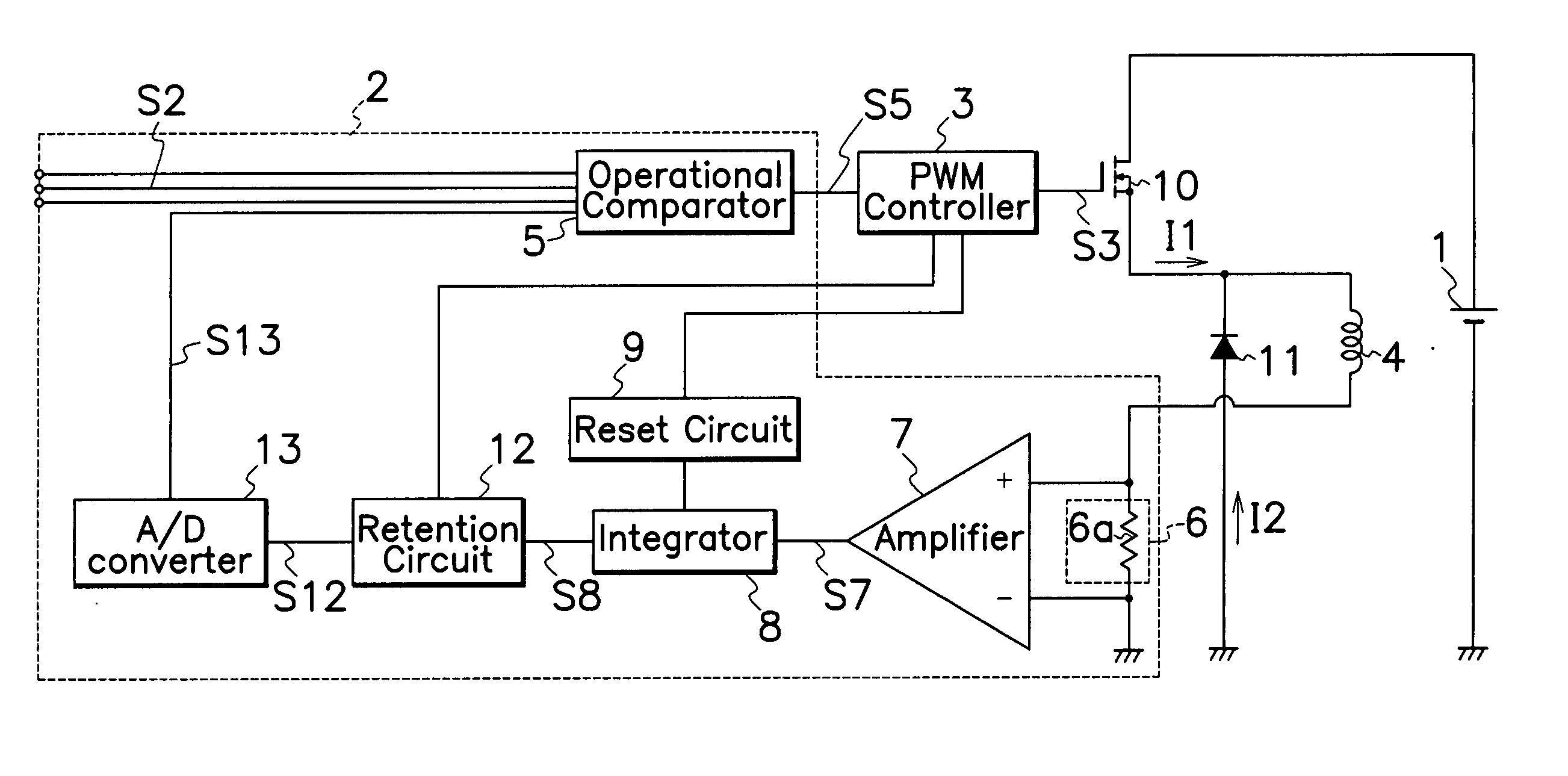
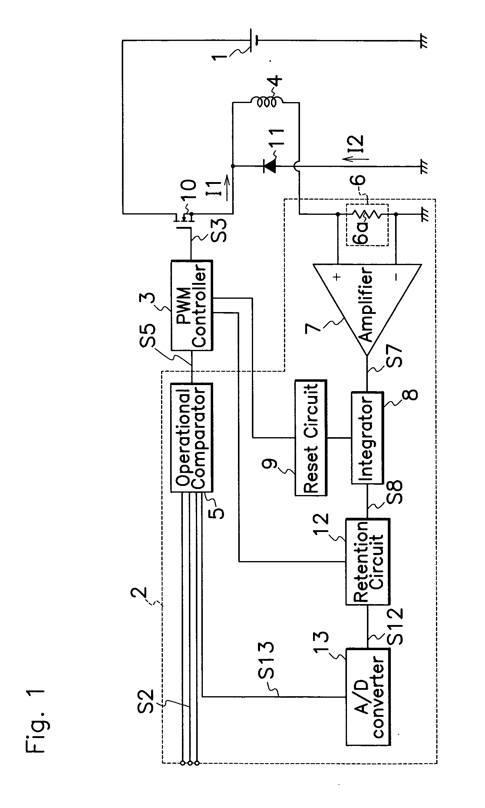
[0016] FIGS. 1 to 3 illustrate an embodiment of the solenoid drive circuit according to the present invention. Same reference symbols as those in FIGS. 4 and 5 are applied in FIGS. 1 to 3 to show the substantially same elements.

[0017] As shown in FIG. 1, a control circuit 2 comprises an integrator 8 for integrating amplified outputs S7 of amplifier 7; a retention circuit 12 for receiving and retaining integrated outputs S8 of integrator 8; an A / D converter 13 for converting outputs S12 from retention circuit 12 into digital signals S13; an operational or computing comparator 5 for receiving outputs S13 from A / D converter 13 and input signals S2 from various sensors of the type same as or similar to the foregoing. Operational comparator 5 calculates the objective value for solenoid current flow based on input signals S2.

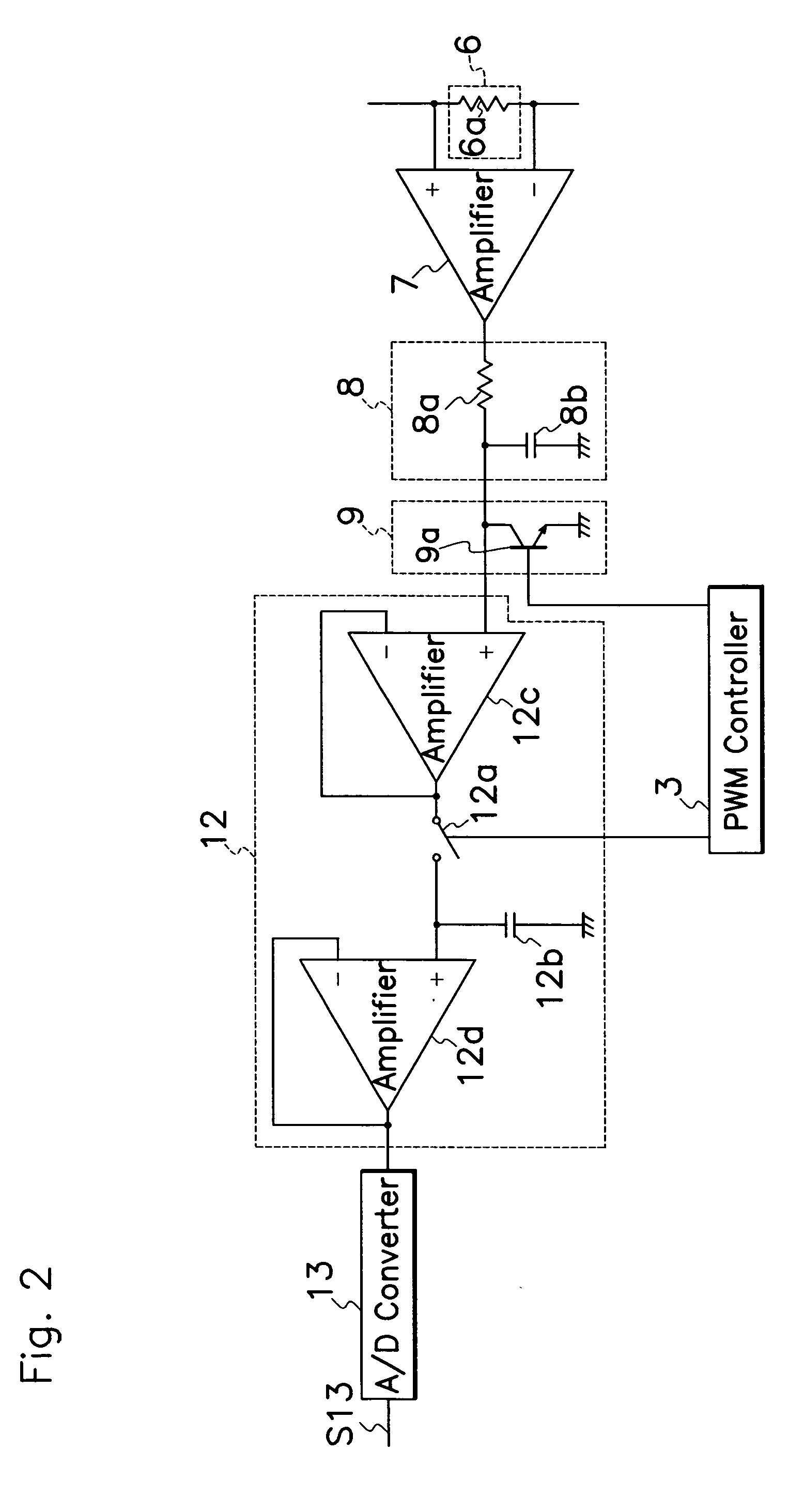
[0018] As shown in FIG. 2, integrator 8 comprises a resistor 8a connected between an output terminal of amplifier 7 and an input terminal of retention circuit 12; a...


PUM

PropertyMeasurementUnit
currentaaaaaaaaaa
electricaaaaaaaaaa
widthaaaaaaaaaa

Abstract

A solenoid drive circuit includes a control circuit 2 which comprises a detector 6 with a resistor 6a for discerning current flow therethrough to produce electric signals that correspond to level of current flow through a solenoid 4 connected to the resistor 6a; an amplifier 7 for amplifying the electric signals from the resistor 6a; and an integrator 8 for integrating the amplified output from the amplifier 7. As integrator 8 is reset each time a PWM controller 3 generates at least one of the successive drive signals S3, an operational comparator 5 receives the latest updated and integrated values S8 of relatively small amount from the integrator 8, easily and promptly compares the updated values S8 from the integrator 8 and an objective current values to produce a deviation of the integrated values S8 from the objective current value, and provides the PWM controller 3 with a command value S5 indicative of the deviation. As the PWM controller 3 provides the control terminal of a MOSFET 10 with the drive signals S3 of pulse width which corresponds to the command value S5 from the operational comparator 5, the current flow through the solenoid 4 can be controlled for accurate activation of the solenoid 4 in good responsiveness to current flow values through the solenoid 4.

Description

TECHINCAL FIELD [0001] This invention relates to a solenoid drive circuit, in particular, of a type capable of controlling current flow through a solenoid in good responsiveness to detected values of current flow through the solenoid with high accuracy. BACKGROUND OF THE INVENTION [0002]FIG. 4 illustrates a prior art solenoid drive circuit which comprises a DC power source 1; a switching element or MOSFET 10 and a solenoid 4 connected in series to DC power source 1; a PWM (Pulse Width Modulation) controller 23 for supplying drive signals S23 of controlled pulse width to a control or gate terminal of n-channel MOSFET 10 to alternately turn on and off MOSFET 10; and a control circuit 22 for producing command signals S25 to PWM controller 23. Control circuit 22 has a detector 6 composed of a resistor 6a which detects current flow I1 through solenoid 4 to produce an electric voltage equivalent to the level of current flow I1. Positive and negative terminals of DC power source 1 are conn...

Claims


Application Information

Patent Timeline
Patent Type & Authority Applications(United States)
IPC IPC(8): H01F7/18H01H47/00H01H47/32
CPCH01F7/1844H01H47/325H01H47/002H01F2007/1888
Inventor SATOH, KIYOKATSUKANAZAWA, MASAKI
Owner SANKEN ELECTRIC CO LTD
Why Eureka
Try Eureka