Method for manufacturing cell

a cell and manufacturing technology, applied in the direction of sustainable manufacturing/processing, wound/folded electrode electrodes, batteries, etc., can solve the problem of short-circuit of the internal cell, and achieve the effect of preventing the generation of foreign matter and preventing deformation

Active Publication Date: 2018-04-05
TOYOTA JIDOSHA KK
View PDF3 Cites 6 Cited by
  • Summary
  • Abstract
  • Description
  • Claims
  • Application Information

AI Technical Summary

Benefits of technology

[0005]In the cell 1 having the foregoing configuration, the relay member 4 has a through hole (air hole) 4c. The space that is formed on the outside of the cell relative to the current interrupting mechanism 5 of the cell case 6 is opened to atmospheric pressure due to this through hole 4c, enabling proper activation of the current interrupting mechanism 5 when the internal pressure of the cell rises. However, according to the knowledge of the inventors of the present invention, when the relay member has the through hole, the inner circumferential surface of the through hole is reduced in its diameter or closes at the time of caulking the shaft portion, and such deformation might create a conductive foreign matter. Entry of the foreign matter into the cell can create an adverse effect on the functioning of the current interrupting mechanism or cause an internal short-circuit of the cell.
[0006]The present invention was contrived in view of these conventional circumstances, and an object thereof is to provide a method for manufacturing a cell that is capable of preventing the generation of a foreign matter by inhibiting deformation of the inner circumferential surface of a tubular shaft portion at the time of the caulking process of the relay member.
[0007]In order to achieve the foregoing object, the method for manufacturing a cell provided by the present invention is a method for manufacturing a cell including: an electrode unit; a cell case that stores the electrode unit; an internal terminal that is stored in the cell case and electrically connected to the electrode unit; an external terminal that is provided on the outside of the cell case; a relay member that has a tubular shaft portion penetrating the cell case and is electrically connected to the internal terminal and the external terminal; and a pressure-type current interrupting mechanism that is disposed between the relay member and the internal terminal and interrupts a current between the internal terminal and the external terminal when an internal pressure of the cell case rises, the method including fixing the relay member and the external terminal to the cell case by caulking the relay member to the external terminal by means of a caulking process. In this manufacturing method, a tubular reinforcing member that is configured with a material harder than that of the relay member is attached to an inner circumferential surface of the tubular shaft portion of the relay member prior to the caulking process, and the caulking process is performed, with the reinforcing member being attached to the inner circumferential surface of the relay member. When caulking the relay member to the external terminal, this manufacturing method can prevent deformation of the inner circumferential surface of the shaft portion by using the tubular reinforcing member attached to the inner circumferential surface of the shaft portion. Therefore, the generation of a foreign matter caused by deformation of the inner circumferential surface of the shaft portion can be prevented.

Problems solved by technology

Entry of the foreign matter into the cell can create an adverse effect on the functioning of the current interrupting mechanism or cause an internal short-circuit of the cell.

Method used


Image

  • Method for manufacturing cell
  • Method for manufacturing cell
  • Method for manufacturing cell

Examples


Embodiment Construction

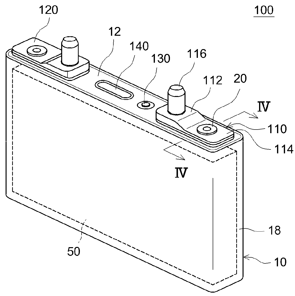
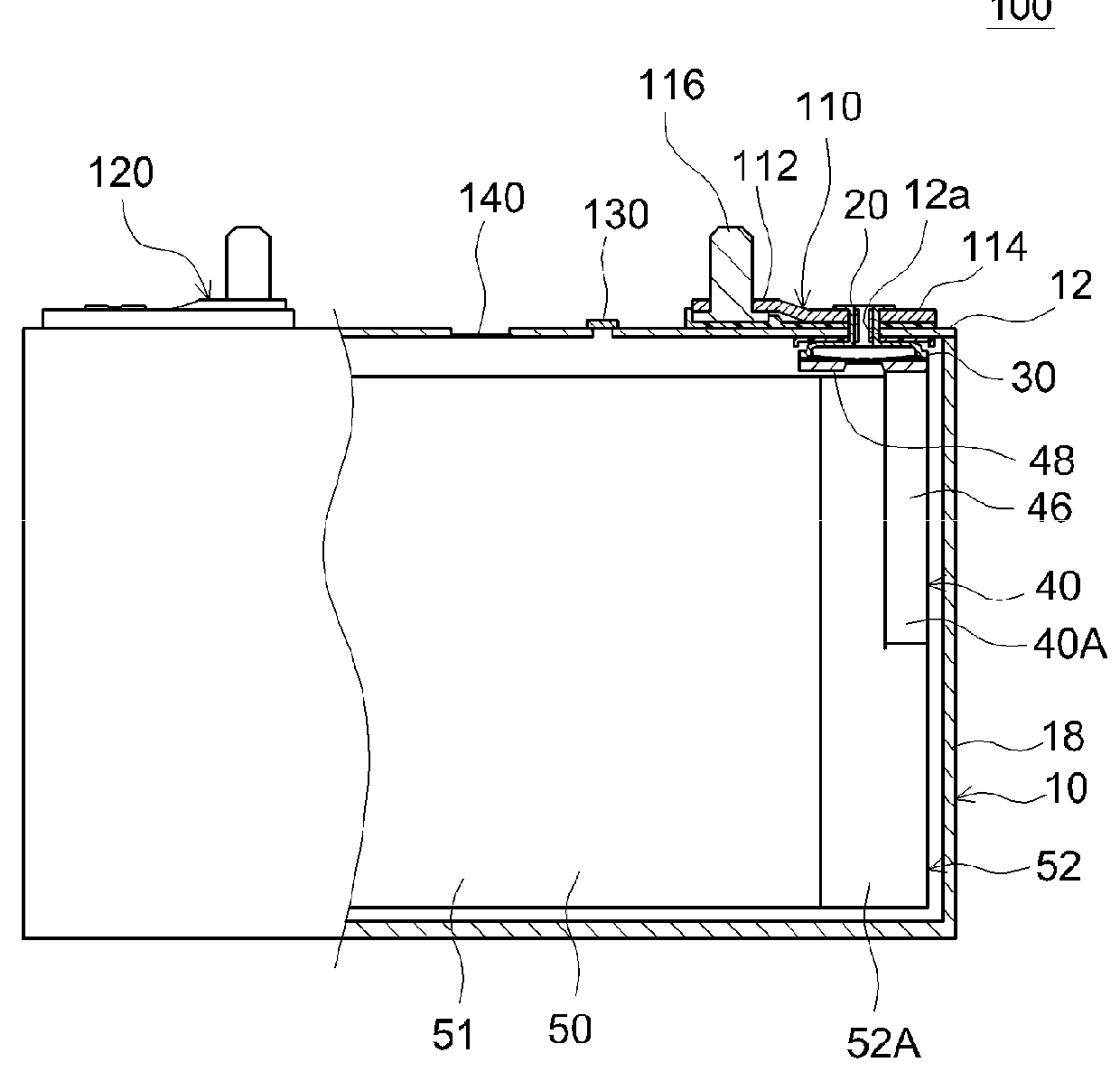
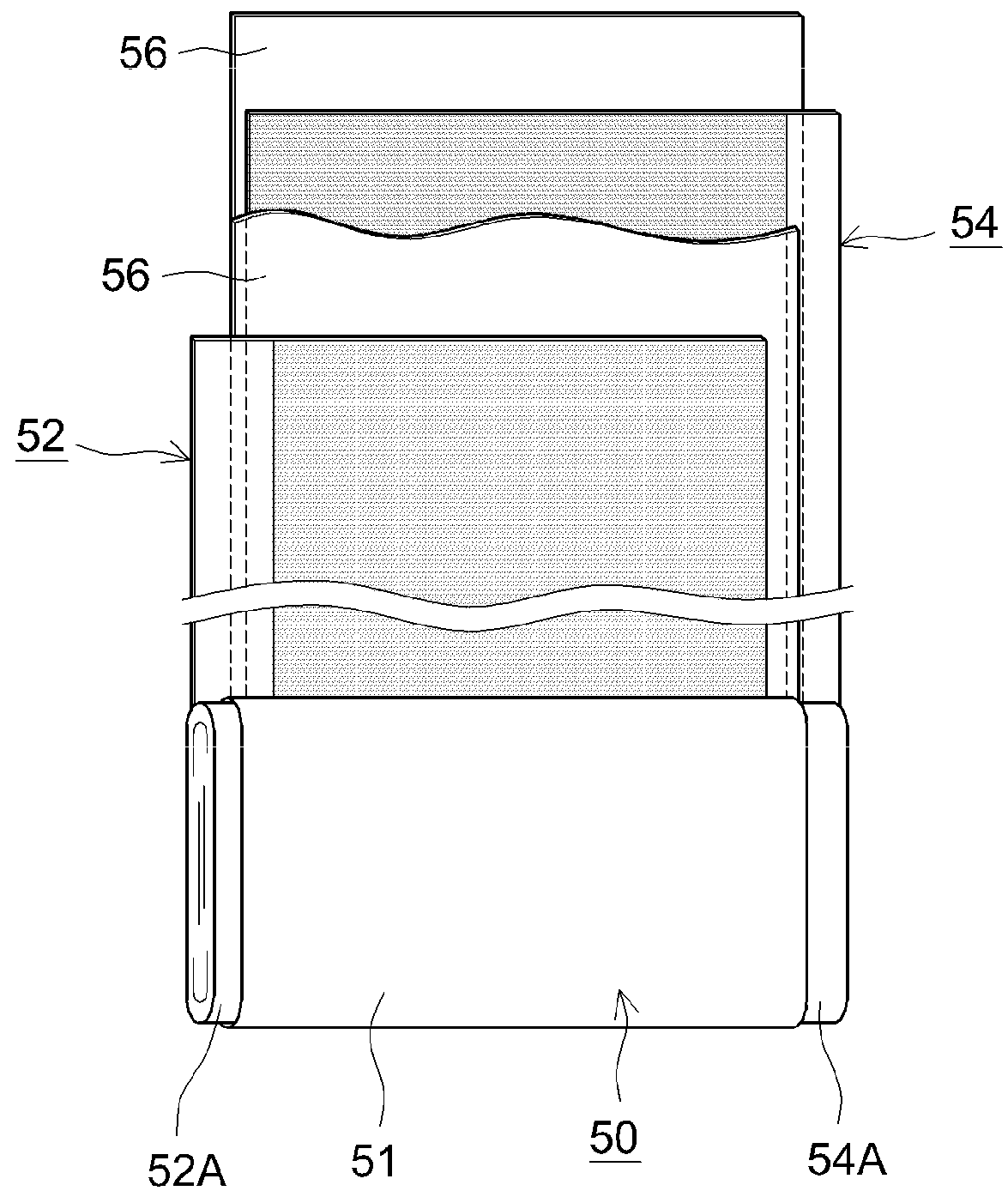
[0015]The present invention disclosed herein is described hereinafter in detail by illustrating embodiments of the present invention with reference to the drawings. Note that in the drawings described below, the members or sections exhibiting the same effects are given the same reference numerals and the overlapping descriptions are often omitted or simplified accordingly. Also, the dimensional relations (lengths, widths, thicknesses, etc.) shown in each drawing does not necessarily reflect the actual dimensional relations. In addition, those matters other than the items that are mentioned particularly in the present specification and required in implementing the present invention can be understood as design items of those skilled in the art that are based on the prior art related to this field.

[0016]A lithium-ion secondary cell is described hereinafter as a preferred embodiment according to the cell disclosed herein; however, the preferred embodiment is not intended to limit the sc...


PUM

PropertyMeasurementUnit
outer diameteraaaaaaaaaa
inner diameteraaaaaaaaaa
Vickers hardnessaaaaaaaaaa

Abstract

In the method for manufacturing a cell according to the present invention, the cell has a cell case, an external terminal, a relay member, and a pressure-type current interrupting mechanism, the method including fixing the relay member and the external terminal to the cell case by caulking the relay member to the external terminal by means of a caulking process. A tubular reinforcing member that is configured with a material harder than that of the relay member is attached to an inner circumferential surface of the tubular shaft portion of the relay member prior to the caulking process, and the caulking process is performed, with the reinforcing member being attached to the inner circumferential surface of the relay member.

Description

CROSS--REFERENCE[0001]The present application claims priority based on Japanese Patent Application No. 2016-196914, filed on Oct. 5, 2016, the entire contents of which are hereby incorporated by reference into the present specification.BACKGROUND OF THE INVENTION1. Field of the Invention[0002]The present invention relates to a method for manufacturing a cell.2. Description of the Related Art[0003]In recent years, secondary cells such as lithium-ion secondary cells and nickel-hydrogen cells have become increasingly important as the in-car power sources that use electricity as power sources or the power sources installed in personal computers, portable terminals and other electrical products. Examples of a typical structure of these secondary cells include a structure in which an electrode unit, which is a power generation element, is sealed in a cell case. This type of cell is generally used in such a manner that the voltage thereof is controlled to fall within a predetermined voltag...

Claims


Application Information

Patent Timeline
Patent Type & Authority Applications(United States)
IPC IPC(8): H01M10/0587H01M2/34H01M10/0525H01M50/176H01M50/528H01M50/533H01M50/534H01M50/55H01M50/553H01M50/562H01M50/564H01M50/567
CPCH01M10/0587H01M2/345H01M10/0525H01M2200/20H01M10/0431H01M10/058H01M50/528H01M50/578H01M50/553H01M50/176H01M50/55H01M50/533H01M50/564H01M50/562H01M50/567H01M50/534H01M10/052Y02E60/10Y02P70/50
Inventor ONO, TOMOHIRO
Owner TOYOTA JIDOSHA KK
Why Eureka
Try Eureka