
Broadcast recording system, recording apparatus, broadcasting apparatus, and recording program for saving storage space of recording medium used for recording contents

a recording system and recording medium technology, applied in the field of broadcast recording systems, can solve the problems of increased storage capacity, increased cost, and reduced user convenience, and achieve the effect of increasing user convenien

Inactive Publication Date: 2005-05-19
SOVEREIGN PEAK VENTURES LLC
View PDF4 Cites 89 Cited by
  • Summary
  • Abstract
  • Description
  • Claims
  • Application Information

AI Technical Summary

Benefits of technology

[0019] That is to say, the recording apparatus receives from the distributing apparatus, a distribution content that corresponds to a broadcast content with a substantially equal image quality. With this arrangement, the user can view a content that corresponds to a broadcast content without any loss of image quality while saving the storage space of the recording apparatus that would otherwise be used to actually record the broadcast content.
[0056] Consequently, the recording apparatus which receives a content broadcast from the broadcasting apparatus is allowed to store entry information attached to the broadcast content. Using the entry information, the recording apparatus can later receive a distribution content corresponding to the broadcast content, so that the user can view the received distribution content. Further, since the distributing apparatus distributes a distribution content which is substantially identical to a broadcast content with respect to a substance of the video and audio data and image quality, the storage space of the recording apparatus is significantly saved in comparison with the case where the recording apparatus records all the broadcast contents.

Problems solved by technology

Such a recording apparatus is capable of recording contents in digital form, which is bulky but of high image quality.
Unfortunately, however, increase in the storage capacity inevitably involves increase in the cost.
Yet, it is undesirable to record contents at higher data compression ratio, which leads to another problem of degradation in image quality.

Method used


Image

  • Broadcast recording system, recording apparatus, broadcasting apparatus, and recording program for saving storage space of recording medium used for recording contents
  • Broadcast recording system, recording apparatus, broadcasting apparatus, and recording program for saving storage space of recording medium used for recording contents
  • Broadcast recording system, recording apparatus, broadcasting apparatus, and recording program for saving storage space of recording medium used for recording contents

Examples


embodiment 1

Overview

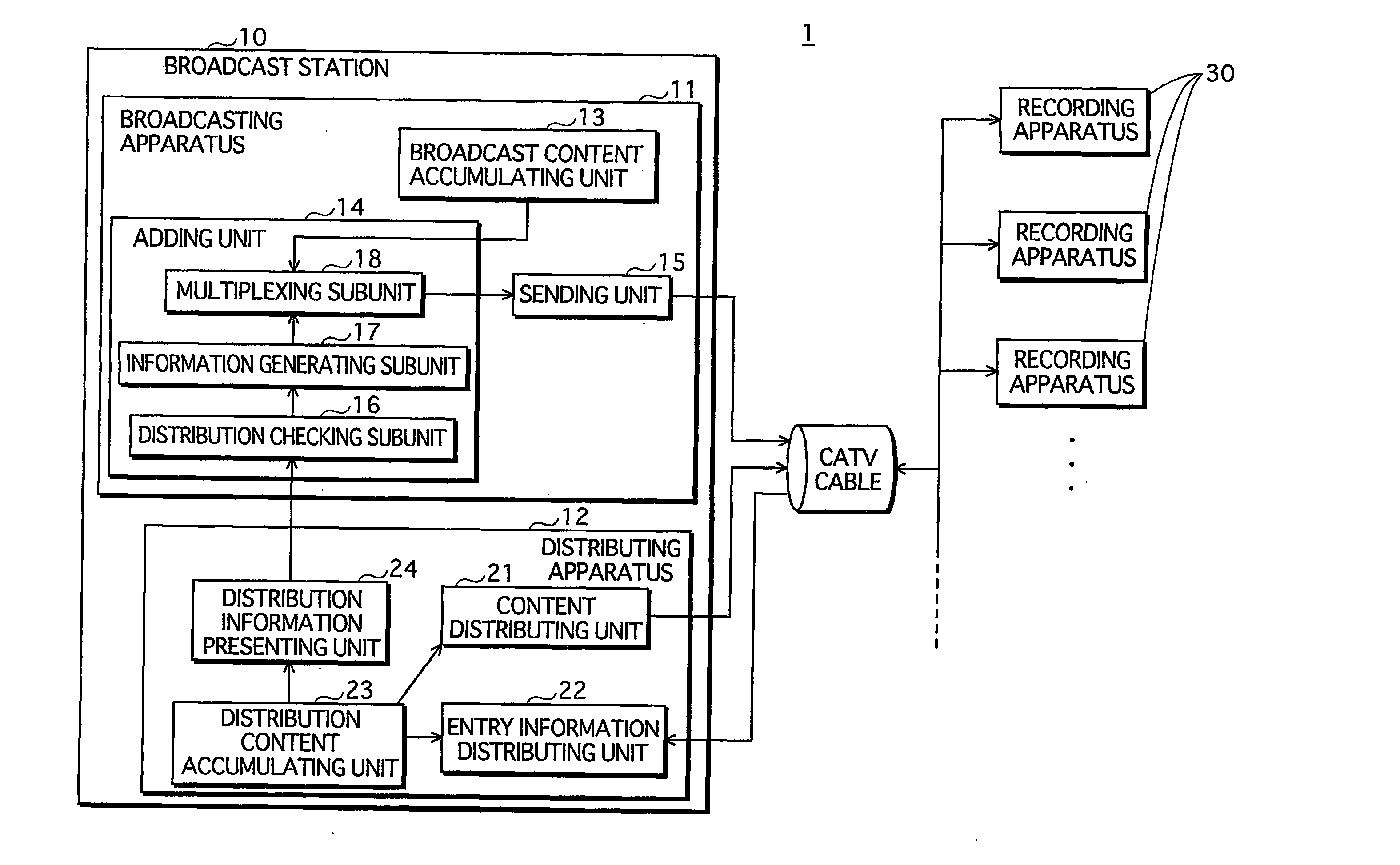
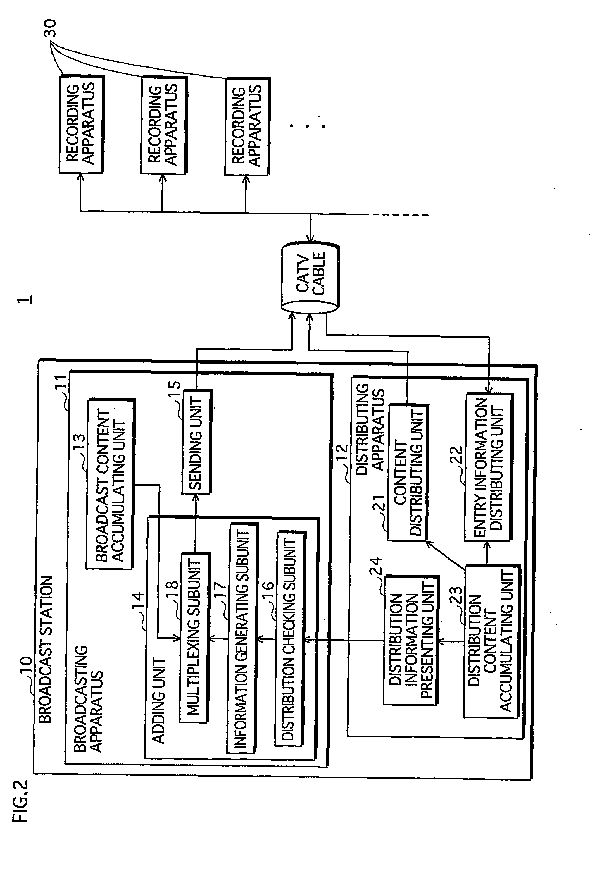
[0081] A broadcast recording system 1 according to an embodiment 1 of the present invention receives contents that are broadcast or distributed on-demand via a cable television (hereinafter, referred to as “CATV”) cable. Users who subscribe to the CATV are allowed to record received contents with a recording apparatus.

[0082] Each broadcast content is attached an identifier of a corresponding content, which is used to request on-demand distribution of that content. The recording apparatus may record an identifier without an actual content. To play back the content, the recording apparatus requests distribution of the content using the identifier so as to receive the content. With this arrangement, the recording apparatus saves a significant amount of the storage space that would otherwise be used to record actual contents.

Structure

1.1 System Configuration

[0083]FIG. 2 is a view showing the configuration of the broadcast recording system 1 according to the embodiment 1 ...

embodiment 2

Overview

[0184] Hereinafter, description is given to a broadcast recording system 2 according to an embodiment 2 of the present invention. The broadcast recording system 2 provides a broadcast service by way of terrestrial analog broadcasting, and an on-demand service via the Internet.

Structure

[0185] 2.1 System Configuration

[0186]FIG. 13 is a view showing the configuration of the broadcast recording system 2 according to the embodiment 2 of the present invention.

[0187] The broadcast recording system 2 is composed of a television broadcast station 40, a recording apparatus 50, and a content distribution centers 60 and 70. According to the broadcast recording system 2, the television broadcast station 40 broadcasts contents, and the recording apparatus 50 receives and records the contents. The television broadcast station 40, the recording apparatus 50, and the content distribution centers 60 and 70 are mutually connected via the Internet.

[0188] The television broadcast station...


PUM


Abstract

An adding unit 14 of a broadcasting apparatus 11 attaches entry information to a content to be broadcast. The entry information specifies a content that is identical to the content to be broadcast out of a plurality of contents available for distribution by a distributing apparatus 12. A sending unit 15 of the broadcasting apparatus 11 broadcasts the content with the entry information attached thereto. An entry information recording unit 106 of a recording apparatus 30 records the entry information that is attached to the received content to a hard disk 104, and a requesting unit 107 requests the distributing apparatus 12 to distribute the content specified by the recoded entry information. A content distributing unit 21 of the distributing apparatus 12 receives the distribution request, and distributes the requested content to the recording apparatus 30. The recording apparatus 30 plays back the distributed content.

Description

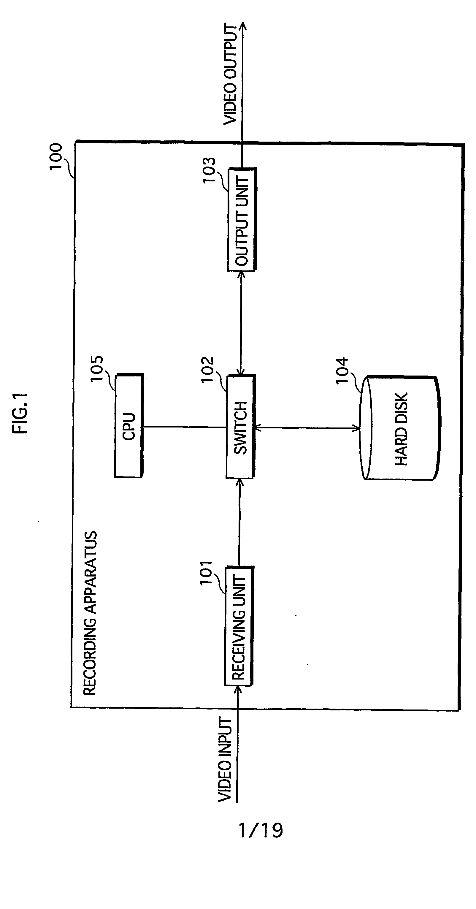
TECHNICAL FIELD [0001] The present invention relates to a broadcast recording system for recording broadcast contents for time-shift viewing. More particularly, the present invention relates to technology to reduce the storage space of a recording medium used to record the contents. BACKGROUND ART [0002] In addition to real-time viewing, viewers of TV broadcasts are allowed to record contents with a recording apparatus for the purpose of time-shift viewing at their convenience. [0003] JP Translation of International Application Publication No. 2002-521978 (page 13, FIG. 1) discloses technology for recording contents to a recording medium such as a hard disk in digital form and for playback of recorded contents. [0004]FIG. 1 is a view showing the structure of a conventional recording apparatus 100. The recording apparatus 100 is composed of functional blocks of a receiving unit 101, a switch 102, an output unit 103, a hard disk 104, and a CPU 105. [0005] The receiving unit 101 conver...

Claims


Application Information

Patent Timeline
IPC IPC(8): G11B27/034G11B27/10H04N5/76H04N5/781H04N5/782H04N5/85H04N7/173H04N7/24H04N9/804
CPCG11B27/034H04N21/84G11B2220/213G11B2220/216G11B2220/2541G11B2220/2545G11B2220/2562G11B2220/2575H04N5/76H04N5/781H04N5/85H04N7/17327H04N9/8042H04N21/235H04N21/23614H04N21/4147H04N21/433H04N21/4334H04N21/4335H04N21/435H04N21/47202H04N21/47214H04N21/6125H04N21/6581H04N21/8352G11B27/105H04N7/08H04N5/92
Inventor KOBAYASHI, YOSHIKAZU
Owner SOVEREIGN PEAK VENTURES LLC
Learn More