Hearing device

a hearing device and hearing technology, applied in the field of hearing devices, can solve the problems that the electro-acoustic requirements often run counter to these conditions, and achieve the effects of less sensitive to body sound, less noise, and convenient replacement of microphones

Active Publication Date: 2005-05-19
SIVANTOS PTE LTD
View PDF17 Cites 26 Cited by
  • Summary
  • Abstract
  • Description
  • Claims
  • Application Information

AI Technical Summary

Benefits of technology

[0009] A further advantage of the one-piece design of the microphone housing with the hearing device housing is that it allows leads which establish electrical contact from the hearing de-vice housing to the microphone housing to be dispensed with. Instead the electrical connection can be made using MID technology directly on the housing. In this case there is the option of using contact springs to establish direct contact between a microphone chip located on a board and the housing.
[0010] Advantageously the microphone is a Silicon microphone. This has the advantage of being much less sensitive to body sound than a conventional microphone such as an electret micro-phone, and is thus of being able to be accommodated without expensive anti-vibration mountings in the hearing device housing.
[0011] In the hearing device a cover can be fitted for acoustic separation of the microphone front volume from the remaining interior space of the hearing device housing. This largely avoids feedback from the hearing unit to the microphone.
[0012] In the inventive hearing device a number of microphones can be additionally arranged on a shared board in the hearing de-vice housing. The manufacture and installation of a single microphone array basically has advantages over individual microphones.
[0013] It can also be advantageous for the microphone or microphones to be arranged on the hearing device board on which the essential components for signal processing of the hearing de-vice are accommodated. This means that the complete electronics of the hearing device can be accommodated on a single board, producing logistical and assembly benefits.
[0014] When the hearing device housing consists of a number of parts, the microphone or microphones can also be fixed to one of these parts and most of the other electronic components of the hearing device can be fixed to another part. The advantage of this is that the microphone can be replaced more quickly when service is required.

Problems solved by technology

Geometrical and electro-acoustic requirements often run counter to these conditions.

Method used


Image

  • Hearing device
  • Hearing device

Examples


Embodiment Construction

[0018] The exemplary embodiments described below represent preferred embodiments of the present invention.

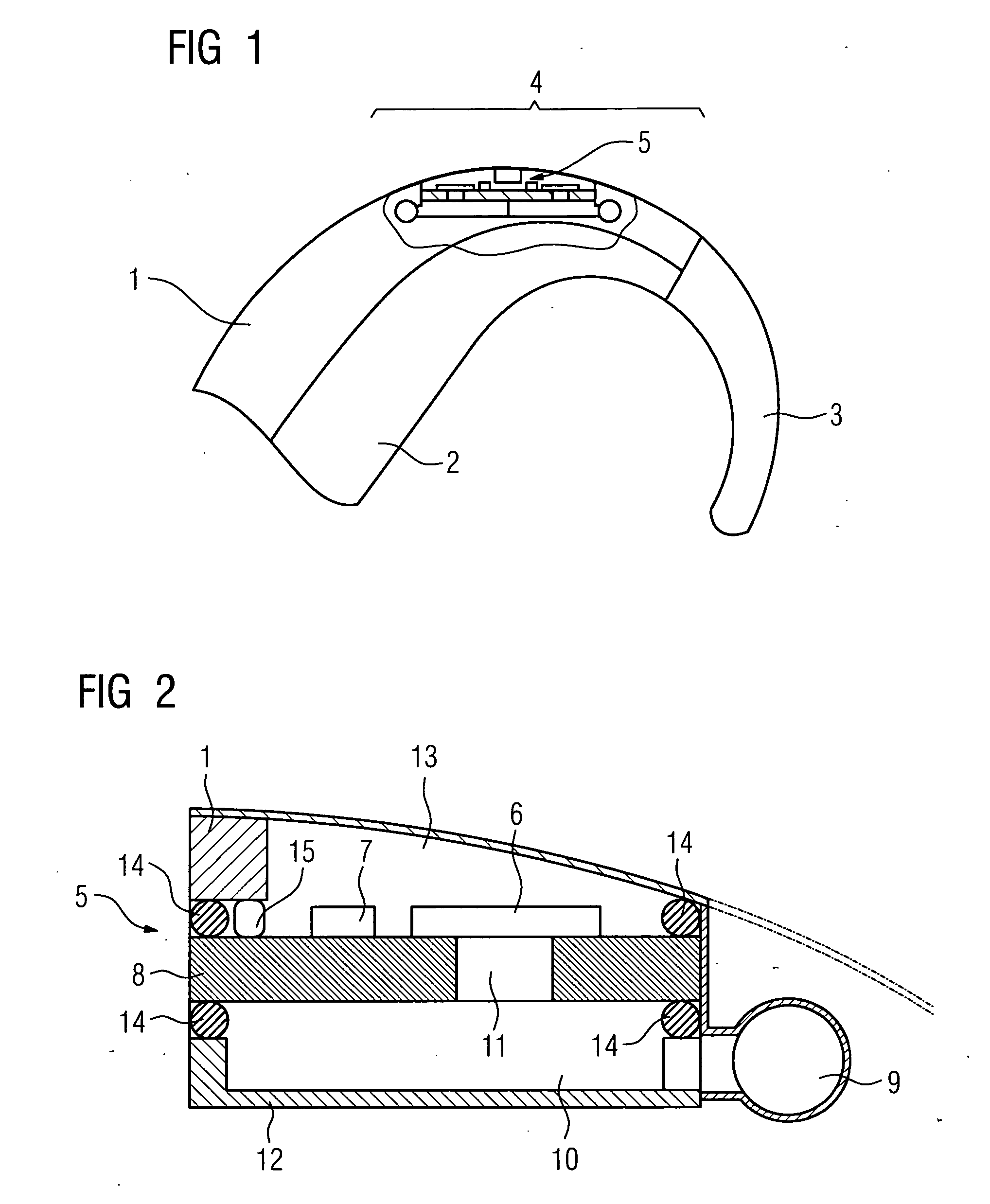
[0019] A behind-the-ear hearing device is embodied in accordance with the example of FIG. 1 with two Silicon microphones. The hearing device possesses a hearing device housing consisting of an upper housing shell half 1 and a lower housing shell half 2. The two housing shell halves 1 and 2 are tapered to-wards the acoustic output and end in a wearer hook 3. The tapered section of the hearing device housing 1, 2 is too narrow for conventional electret microphones so that this must be arranged at a position in the hearing device which is further away from the wearer hook 3. Opposite this a Silicon microphone 5 without separate microphone housing can also be accommodated in the tapered section 4 of the hearing device housing.

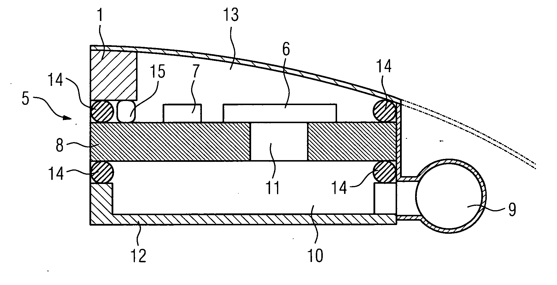
[0020] The Silicon microphone is shown in its fitted state in an enlarged view in FIG. 2. It essentially comprises a Silicon microphone chip 6 and a signal p...


PUM


Abstract

The space in hearing device housings (1, 2) is to be enabled to be used more intensively. To this end, the invention pro-poses dispensing with a separate microphone housing and embodying said housing in one piece with the hearing device housing. To reduce the microphone's sensitivity to body sound the corresponding attenuation can be provided in the hearing device shells or the non body-sound-sensitive Silicon microphones (5).

Description

CROSS REFERENCE TO RELATED APPLICATIONS [0001] This application claims priority to the German application No. 10343292.2, filed Sep. 18, 2003 and which is incorporated by reference herein in its entirety. FIELD OF INVENTION [0002] The present invention relates to a hearing device with a hearing device housing and a microphone which is accommodated in the hearing device housing. BACKGROUND OF INVENTION [0003] For cosmetic reasons hearing aids should be worn as invisibly as possible but their microphones must be installed in an ex-posed place in order to pick up sounds. A further criterion governing the placing and accommodation of microphones in a hearing device is the problem of body noise. Since the hearing unit accommodated in the hearing device generates a significant amount of body noise in addition to the air noise that it generates, the microphones must be mounted so that they are isolated from vibration in order to prevent feed-back. A suitable vibration isolation system take...

Claims


Application Information

Patent Timeline
Patent Type & Authority Applications(United States)
IPC IPC(8): H04R25/00
CPCH04R25/405H04R2225/021H04R25/65H04R25/604H04R25/607
Inventor NIEDERDRANK, TORSTENWEISTENHOFER, CHRISTIAN
Owner SIVANTOS PTE LTD
Why Eureka
Try Eureka