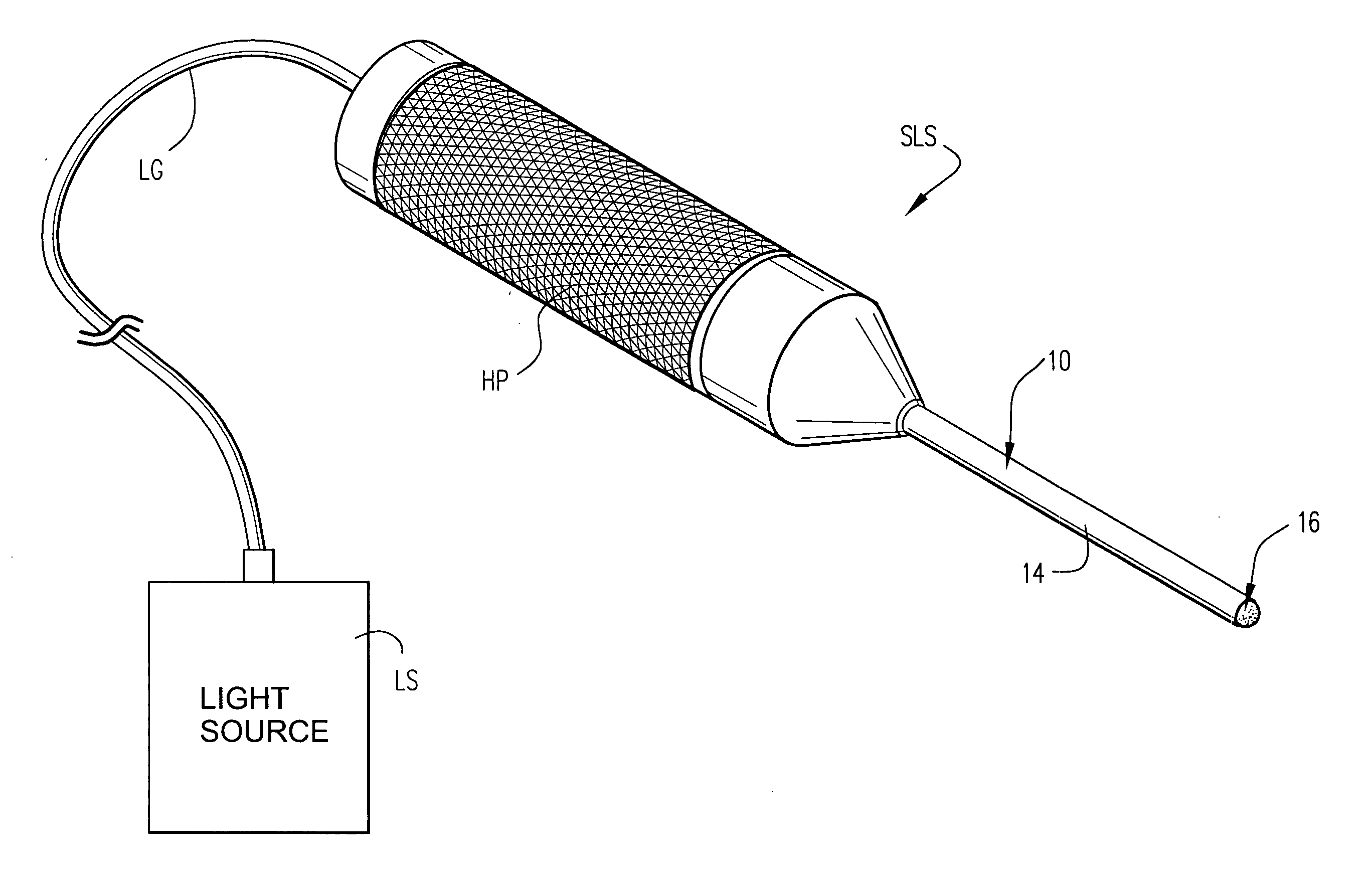
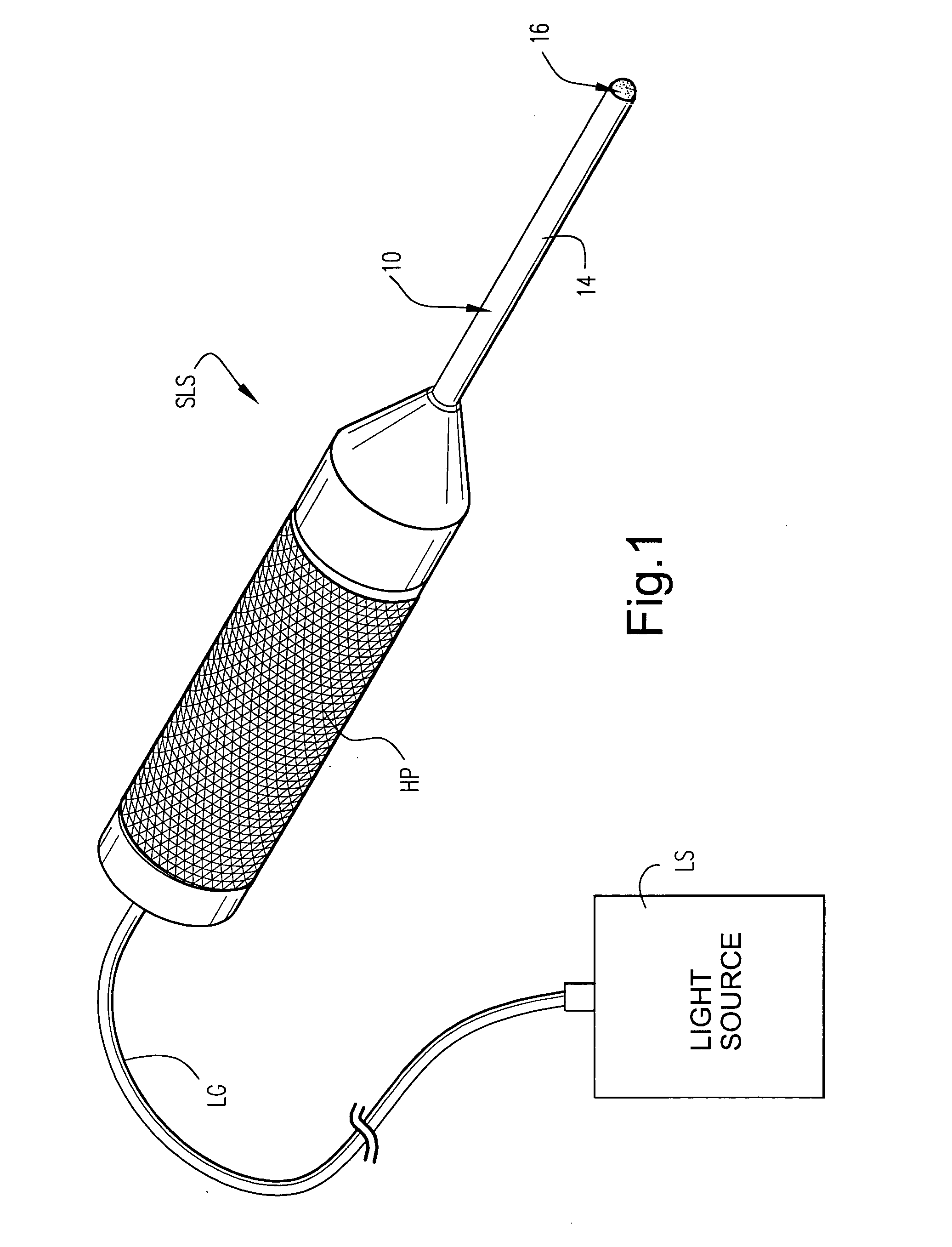
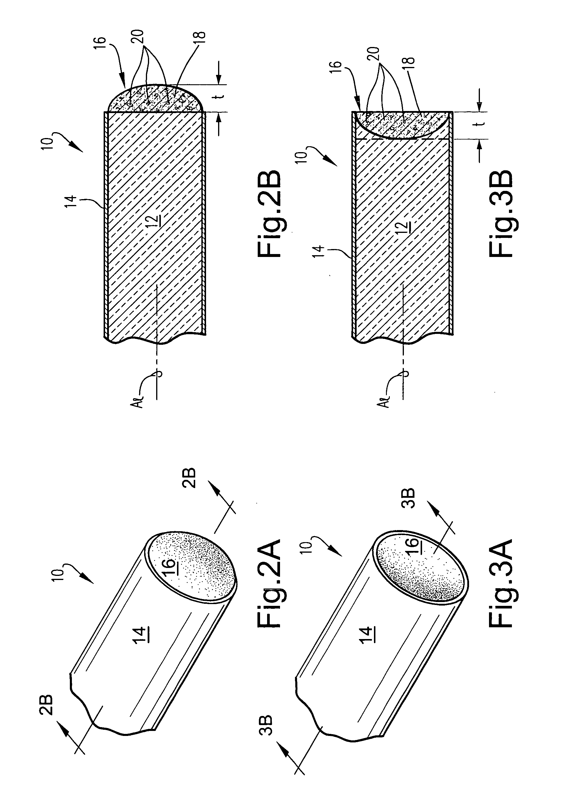
Optical fiber illuminators having integral distal light diffusers especially useful for ophthalmic surgical procedures, and methods of making the same

a technology distal light diffusers, which is applied in the field of optical fiber illuminators, can solve the problems of increasing the risk of retinal exposure to high energy, requiring some complex manufacturing steps, and less than satisfactory light focus, so as to improve the diffusion of light within the eye

Inactive Publication Date: 2005-05-19
DUKE UNIV
View PDF8 Cites 41 Cited by
  • Summary
  • Abstract
  • Description
  • Claims
  • Application Information

AI Technical Summary

Benefits of technology

[0002] Current fiber optic illumination used for intra ocular surgery includes a range of fiber optic options such as plain blunt fiber tips, round ball, cannonball, bullet tip probes with a modified curvature of the tip for diffusion, or an individual lens separate from the fiber to create diffusion. These prior proposals allow for fiber optic guided light to be directed into the eye, and in the case of the two latter examples noted previously, there is improved diffusion of the light within the eye.

Problems solved by technology

Focussing of light is less than satisfactory during ophthalmic surgical procedures as it can increase the risk of retinal exposure to high energy if the tip is moved close to the retina.
Such a conventional fiber optic probe, however, has the possibility of focusing down and having higher intensity light on the retina, however some systems use a holographically manufactured micro lens array that diffuses the illumination without having any focal spot of intense radiance.
Such a lens system however, requires some complex manufacturing steps to position the fiber and the lens within the same instrument.
Moreover, it has some restrictions because the space between the fiber and lens needs to remain fluid-free and there is throughput loss at the fiber optic-to-air-to-lens interfaces.

Method used


Image

  • Optical fiber illuminators having integral distal light diffusers especially useful for ophthalmic surgical procedures, and methods of making the same
  • Optical fiber illuminators having integral distal light diffusers especially useful for ophthalmic surgical procedures, and methods of making the same
  • Optical fiber illuminators having integral distal light diffusers especially useful for ophthalmic surgical procedures, and methods of making the same

Examples


examples

1. Diffusion Fiber Manufacturing Technique:

[0035] 20 fiber optic light guides (FOLGs) commercially obtained from Alcon Laboratories, Inc. of Fort Worth, Tex. (#812-1421-002), were wet lapped using first 320 grit sandpaper and then 600 grit sandpaper to ensure that the fiber optic probe tips were flat and thereby provide maximum efficiency and allow for strong adhesion. After lapping, each fiber was then measured for maximum light throughput using an EG&G, model 555-75 integrating sphere in conjunction with a Lutron, model LX-101, Lux meter. The fibers were then each assigned one of the possible combinations of the letters A through E and the numbers 2, 5, 10, and 20 to allow for future identification. The number designations corresponded to the thickness, in thousandths of an inch, of the light diffusing medium that would be applied to each FOLG. Therefore, five fibers each provided with a light diffusing medium layer thickness of 2 thousandths of an inch (0.002″), 5 thousandths o...


PUM

PropertyMeasurementUnit
vol. %aaaaaaaaaa
vol. %aaaaaaaaaa
vol. %aaaaaaaaaa

Abstract

Optical fiber illuminators are embodied in light-diffusing particles affixed to an optical fiber's terminal end. Most preferably, the light-diffusing particles are optically transparent solid particles dispersed symmetrically or asymmetrically in an optically transparent bonding material to thereby form a light diffusion medium (LDM). The solid particles may thus be dispersed in the bonding material while the bonding material is in a liquid state to form the LDM. A mass of the LDM may thus be applied onto the terminal optical fiber end while the bonding material is in such a liquid state. Allowing the bonding material to solidify will therefore affix the light-diffusing particles to the terminal end of the optical fiber. In such a manner, optical fiber illuminators having high light throughput and diffusion may be made.

Description

FIELD OF THE INVENTION [0001] The present invention relates generally to the field of optical fiber illuminators, that is, optical fibers which guide light from a remote light source to a terminal end of the optical fiber so as to provide desired illumination. In especially preferred forms, the present invention relates to fiber optic illuminators that have particular utility in the medical field, such as, to illuminate a surgical site, especially during ophthalmic surgical procedures. BACKGROUND AND SUMMARY OF THE INVENTION [0002] Current fiber optic illumination used for intra ocular surgery includes a range of fiber optic options such as plain blunt fiber tips, round ball, cannonball, bullet tip probes with a modified curvature of the tip for diffusion, or an individual lens separate from the fiber to create diffusion. These prior proposals allow for fiber optic guided light to be directed into the eye, and in the case of the two latter examples noted previously, there is improve...

Claims


Application Information

Patent Timeline
Patent Type & Authority Applications(United States)
IPC IPC(8): G02B6/26
CPCG02B6/262
Inventor NAPPI, RICHARD B.OVERAKER, RONALD F.TOTH, CYNTHIA A.DODGE, BRIAN C.NGYUEN, HOANGWINTER, KATRINA P.
Owner DUKE UNIV
Why Eureka
Try Eureka