Electrowetting battery having a nanostructured electrode surface

a technology of nanostructured electrodes and batteries, applied in the field of batteries, can solve problems such as battery depletion

Active Publication Date: 2005-05-19
ALCATEL-LUCENT USA INC
View PDF7 Cites 21 Cited by
  • Summary
  • Abstract
  • Description
  • Claims
  • Application Information

AI Technical Summary

Benefits of technology

[0004] We have realized that it would be extremely advantageous to be able to prevent the discharge of batteries while the batteries are not in use. Additionally, it would be advantageous to be able to variably control when the discharge of the batteries was initiated.

Problems solved by technology

Thus, a battery can become depleted over a period of time even when it is not in active use in an electrical circuit.

Method used


Image

  • Electrowetting battery having a nanostructured electrode surface
  • Electrowetting battery having a nanostructured electrode surface
  • Electrowetting battery having a nanostructured electrode surface

Examples


Embodiment Construction

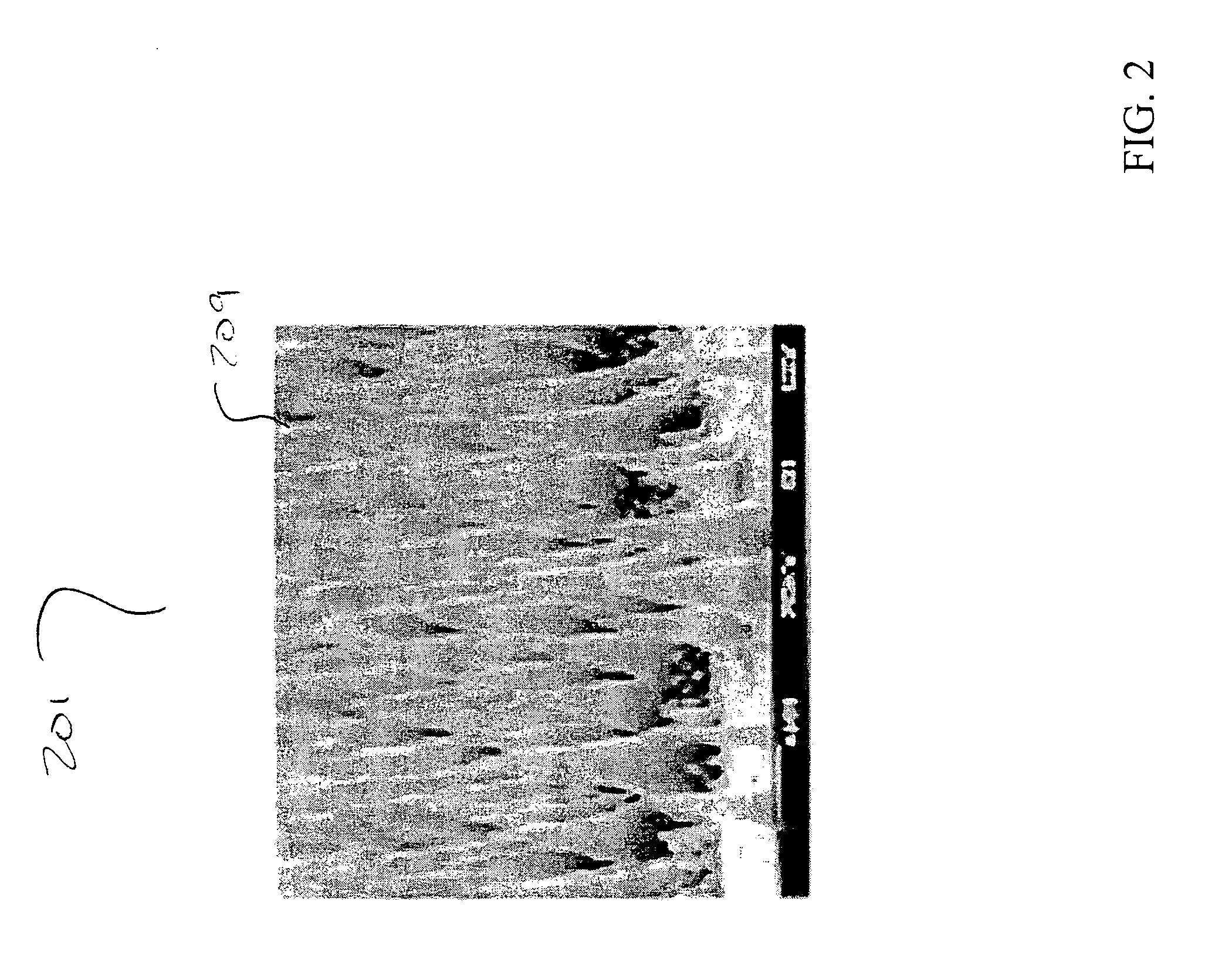
[0018]FIG. 2 shows an illustrative nanopost pattern 201 with each nanopost 209 having a diameter of less than 1 micrometer. While FIG. 2 shows nanoposts 209 formed in a somewhat conical shape, other shapes and sizes are also achievable. In fact, cylindrical nanopost arrays have been produced with each nanopost having a diameter of less than 10 nm. Specifically, FIGS. 3A-3E show different illustrative arrangements of nanoposts produced using various methods and further show that such various diameter nanoposts can be fashioned with different degrees of regularity. Moreover, these figures show that it is possible to produce nanoposts having various diameters separated by various distances. An illustrative method of producing nanoposts, found in U.S. Pat. No. 6,185,961, titled “Nanopost arrays and process for making same,” issued Feb. 13, 2001 to Tonucci, et al, is hereby incorporated by reference herein in its entirety. Nanoposts have been manufactured by various methods, such as by u...


PUM

PropertyMeasurementUnit
diameteraaaaaaaaaa
diameteraaaaaaaaaa
diameteraaaaaaaaaa

Abstract

A method and apparatus are disclosed wherein a battery comprises an electrode having at least one nanostructured surface. The nanostructured surface is disposed in a way such that an electrolyte fluid of the battery is prevented from contacting the electrode, thus preventing discharge of the battery when the battery is not in use. When a voltage is passed over the nanostructured surface, the electrolyte fluid is caused to penetrate the nanostructured surface and to contact the electrode, thus activating the battery. In one illustrative embodiment, the battery is an integrated part of an electronics package. In another embodiment, the battery is manufactured as a separate device and is then brought into contact with the electronics package. In yet another embodiment, the electronics package and an attached battery are disposed in a projectile that is used as a military targeting device.

Description

FIELD OF THE INVENTION [0001] The present invention relates generally to batteries and, more particularly, to batteries having at least one nanostructured electrode surface. BACKGROUND OF THE INVENTION [0002] Many beneficial devices or structures in myriad applications rely on batteries as a power source. As shown in FIG. 1, illustrative liquid-cell battery 101, is characterized by an electrolyte liquid 102 which provides a mechanism for an electrical charge to flow in direction 103 between a positive electrode 104 and a negative electrode 105. When such a battery 101 is inserted into an electrical circuit 106 with illustrative load 108, it completes a loop which allows electrons to flow uniformly in direction 107 around the circuit 106. The positive electrode thus receives electrons from the external circuit 106. These electrons then react with the materials of the positive electrode 104 in reduction reactions that generate the flow of a charge to the negative electrode 105 via ion...

Claims


Application Information

Patent Timeline
Patent Type & Authority Applications(United States)
IPC IPC(8): H01M4/02F42B12/38F42C19/00H01M4/06H01M6/30H01M6/32H01M6/36
CPCF42C19/00H01M6/36H01M6/32H01M6/30H01M4/02
Inventor KROUPENKINE, TIMOFEI NIKITATAYLOR, JOSEPH ASHLEYWEISS, DONALD
Owner ALCATEL-LUCENT USA INC
Why Eureka
Try Eureka