
System and method for distortion reduction in an electromagnetic tracker

Inactive Publication Date: 2005-05-19
GENERAL ELECTRIC CO
View PDF2 Cites 96 Cited by
  • Summary
  • Abstract
  • Description
  • Claims
  • Application Information

AI Technical Summary

Benefits of technology

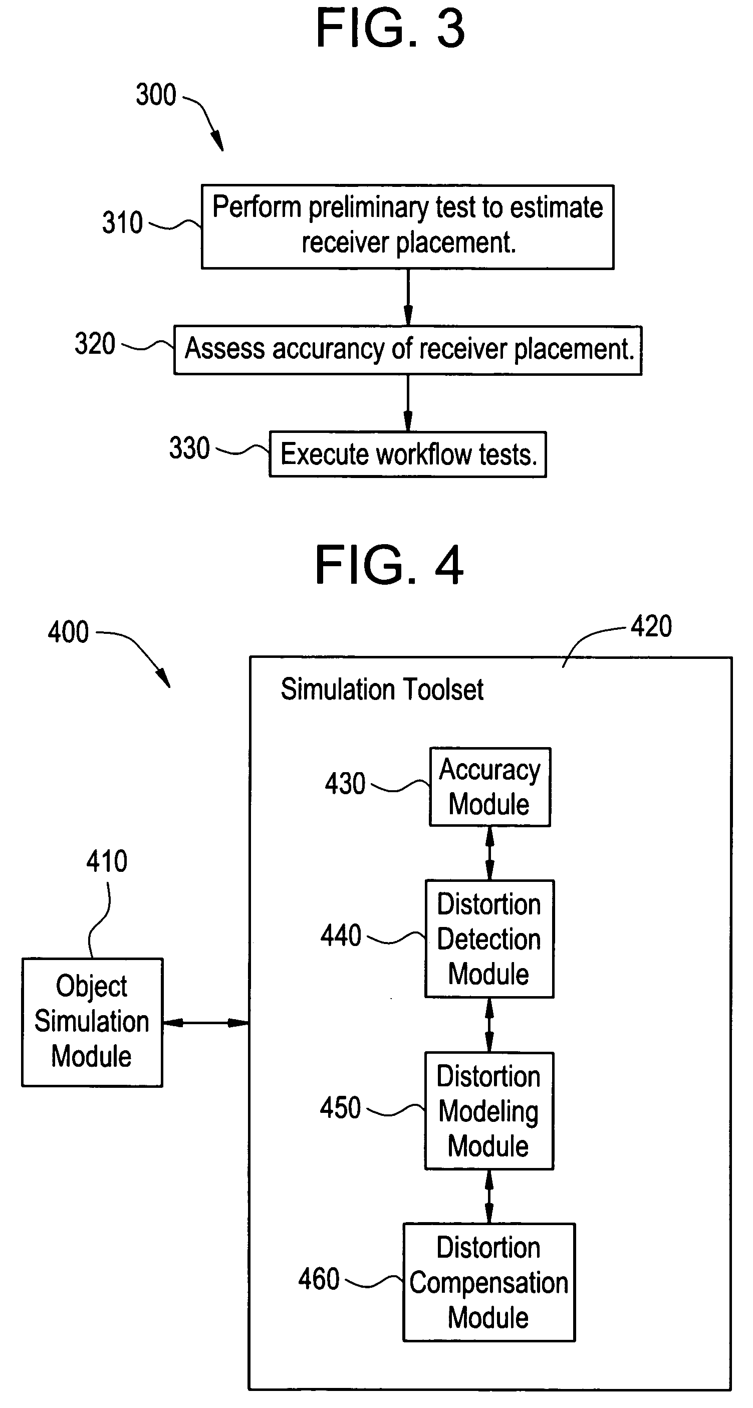
[0017] A certain embodiment of a virtual tracking system includes an object simulation module for simulating an object to be tracked and a simulation toolset for analyzing at least one distortion characteristic of the object. The simulation toolset is capable of generating distortion information for the object based on the distortion characteristic(s). In an embodiment, the simulation toolset includes an accuracy module for determining accuracy of simulated tracking of the object. The simulation toolset may include a distortion detection module for determining an impact of distortion from the object on tracking accuracy. The simulation toolset may also include a distortion modeling module for generating an electromagnetic model for evaluating a distorting effect of the object on a tracker environment. Additionally, the simulation toolset may include a distortion compensation module for improving distortion tolerance of an electromagnetic tracker.

Problems solved by technology

That is, a tracking system may be used in other settings where the position of an instrument in an object or an environment is difficult to accurately determine by visual inspection.
Distortions in the electromagnetic tracking system may cause the tracking system to be inaccurate.
Distortion may produce inaccurate position measurements and potential danger to a patient.

Method used


Image

  • System and method for distortion reduction in an electromagnetic tracker
  • System and method for distortion reduction in an electromagnetic tracker
  • System and method for distortion reduction in an electromagnetic tracker

Examples


Embodiment Construction

[0025] For the purpose of illustration only, the following detailed description references an embodiment of an electromagnetic tracking system used with an image-guided surgery system. It is understood that the present invention may be used with other imaging systems and other applications.

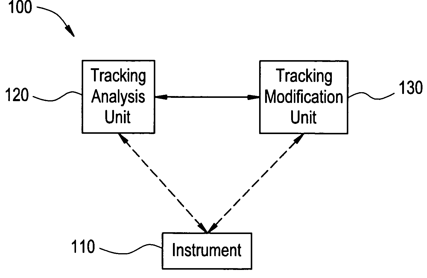
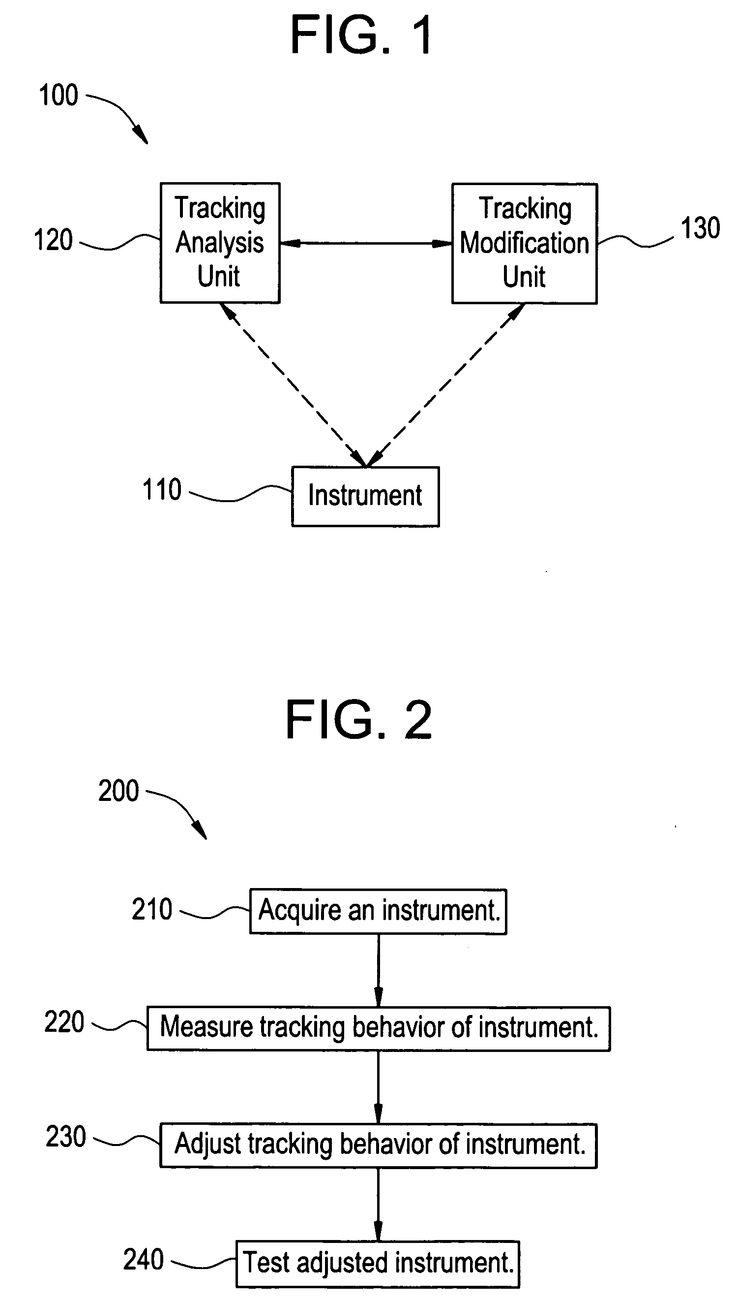
[0026]FIG. 1 illustrates a distortion handling system 100 for use in improving position measurement accuracy in an electromagnetic (EM) tracker used in accordance with an embodiment of the present invention. The system 100 includes an instrument 110, a tracking analysis unit 120, and a tracking modification unit 130. The tracking analysis unit 120 observes the tracking behavior of the instrument 110. The tracking modification unit 130 attempts to improve or compensate for the tracking behavior of the instrument 110 based on information from the tracking analysis unit 120. The tracking analysis unit 120 and the tracking modification unit 130 may be implemented in hardware and / or in software as sep...


PUM


Abstract

Certain embodiments of the present invention provide a system and method for distortion analysis and reduction in an electromagnetic tracker. Certain embodiments of the system include a tracking analysis unit for analyzing a tracking behavior of an instrument and a tracking modification unit for compensating for the tracking behavior of the instrument. The tracking modification unit may compensate for the tracking behavior of the instrument by adjusting the tracking behavior of the instrument. The tracking modification unit may also compensate for the tracking behavior of the instrument by adjusting a tracking system for tracking the instrument. The tracking analysis unit may test the adjusted tracking behavior of the instrument. In an embodiment, the tracking analysis unit generates a map and / or a model of a distortion characteristic of the instrument. The distortion characteristic may be a magnetic field. The distortion handling system is a computer simulated distortion handling system.

Description

RELATED APPLICATIONS [0001] The present application relates to, and claims priority from, U.S. Provisional Application No. 60 / 520,138 filed on Nov. 12, 2003, and entitled “System and Method for Distortion Reduction in an Electromagnetic Tracker” (Attorney Docket Number 1333165NV).FEDERALLY SPONSORED RESEARCH OR DEVELOPMENT [0002] [Not Applicable]MICROFICHE / COPYRIGHT REFERENCE [0003] [Not Applicable]BACKGROUND OF THE INVENTION [0004] The present invention generally relates to an electromagnetic tracking system. In particular, the present invention relates to a system and method for reducing distortion caused by tools and other elements in an electromagnetic tracking system. [0005] Medical practitioners, such as doctors, surgeons, and other medical professionals, often rely upon technology when performing a medical procedure, such as image-guided surgery or examination. A tracking system may provide positioning information for the medical instrument with respect to the patient or a re...

Claims


Application Information

Patent Timeline
IPC IPC(8): A61B5/06G01B7/004G01S5/02G01S19/04G01V3/10G01V13/00
CPCA61B5/06G01S5/0215A61B2019/5251A61B6/487A61B19/5244G01V13/00A61B34/20A61B2034/2051A61B5/062A61B2562/17
Inventor ANDERSON, PETER TRANEUS
Owner GENERAL ELECTRIC CO
Learn More