G-tube retainer

a technology of retaining device and gastrostomy tube, which is applied in the field of gastrostomy tube, can solve the problems of limited brain function of g-tube recipients, lack of suitable means available, lack of capacity to understand not to pull on or pull out the g-tube, etc., and achieve the effect of convenient and flexible us

Inactive Publication Date: 2005-05-19
ENROTH LORANA A M
View PDF12 Cites 6 Cited by
  • Summary
  • Abstract
  • Description
  • Claims
  • Application Information

AI Technical Summary

Benefits of technology

[0008] In a second embodiment, the g-tube retainer of the present invention includes a patient base and an elongate venting tube extension cover. The patient base and venting tube extension cover are preferably formed as separate parts that are connectable to one another with fasteners on corresponding ends to provide for more flexibility of care by the caregiver and less disturbance of the g-tube recipient during caregiving. The fasteners may include Velcro®, snaps, buttons, hooks and loops, and the like. The patient base and extension tube cover preferably include batting material, foam padding, or the like. In an operative mode, the patient base and extension tube cover are generally tubular or cylindrical in shape and surround the g-tube retention button and venting tube extension. The patient base and extension tube cover may include fasteners, such as Velcro®, snaps, buttons, hooks and loops, that may be disengaged in a inoperative mode to enable the patient base and extension tube cover to unroll to allow for cleaning or provide other functions. Like the first embodiment, the patient base is held in position on the patient with an adjustable torso wrap and the venting tube extension cover includes a passageway that is lined with a material, such as plastic and the like, that tends to slide along the g-tube venting tube extension as the g-tube recipient grabs the venting tube extension cover and attempts to pull on the g-tube venting tube extension.
[0010] I another aspect, the g-tube retainer of the present invention may include a mounting loop and band to conveniently and flexibly position the g-tube and retainer in a number of desired positions for such functions as regular feeding or upright fully vented feeding.

Problems solved by technology

Thus, a large percentage of the g-tube recipients, whether children or adults suffering from limited brain function, lack the capacity to understand not to pull on or pull out the g-tube.
Unfortunately, there is no suitable means available to prevent these patients from pulling on the g-tube, whether accidentally or intentionally, which could make the area sore and / or potentially pull the g-tube out.
However, most patients easily remove this “rigging” in their attempts to pull the g-tube out.
This is especially difficult for even the most attentive caregiver.
In addition to the retention problem, there is no suitable means available to comfortably orient the g-tube in an upright and fully vented position.
However, such a “rigging” inhibits movement of the patient more than a few inches.

Method used


Image

  • G-tube retainer
  • G-tube retainer
  • G-tube retainer

Examples


Embodiment Construction

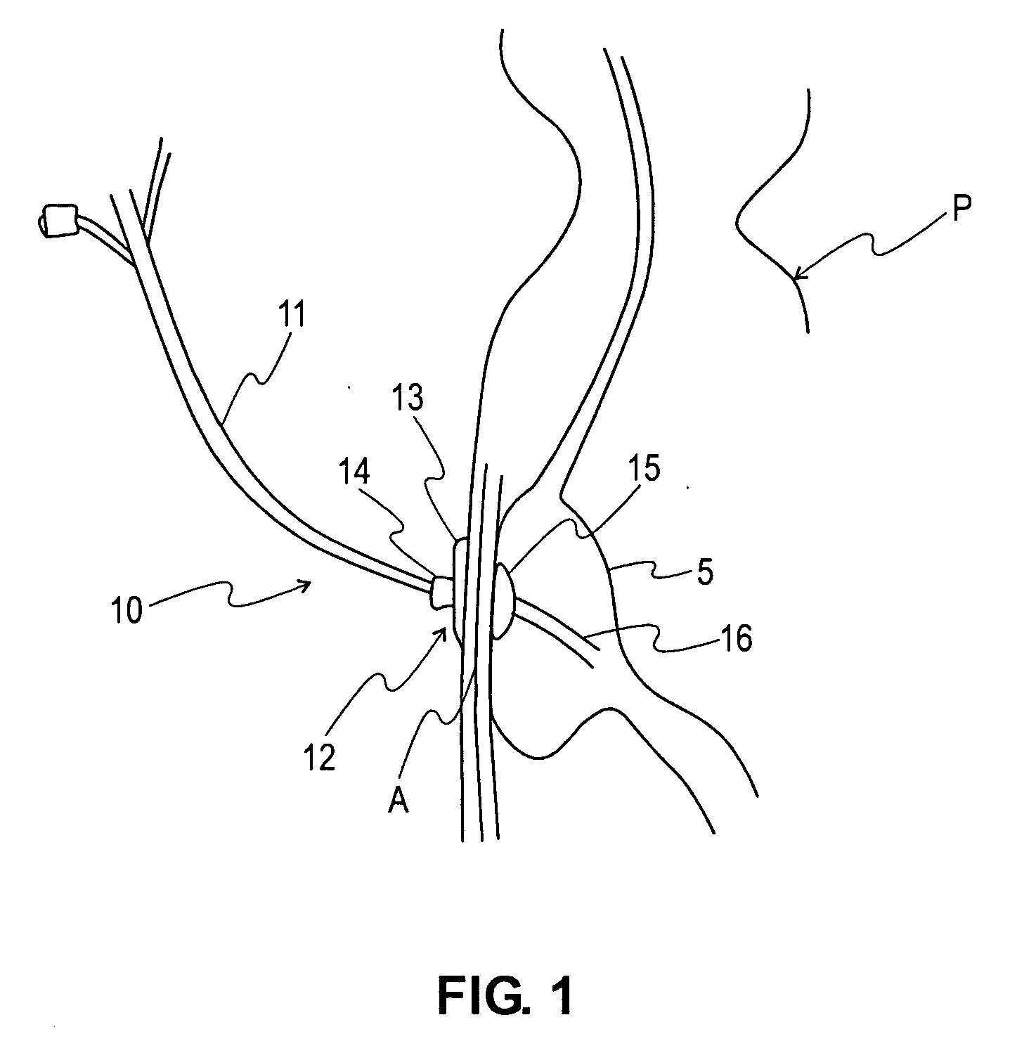
[0023] Referring to FIG. 1, a typical gastrostomy tube or “g-tube”10 is shown implanted in a patient P. The g-tube 10 includes a tube 16 anchored in position in the patient's stomach S with a balloon 15. The g-tube 10 is further held in position via a retention button 12 positioned exterior to the patient's abdominal wall A opposing the balloon 15. The retention button 12 comprises a base 13, typically disc-shaped, positioned against the patient's abdominal wall A and a tube neck 14 extending outwardly therefrom. A g-tube venting tube extension 11 extends from the tube neck 14.

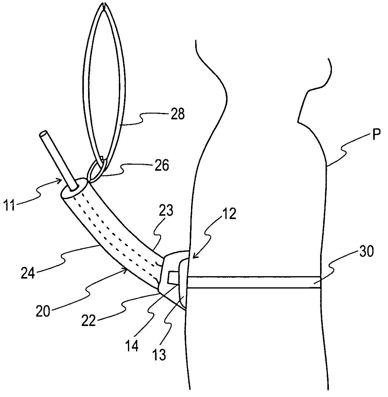
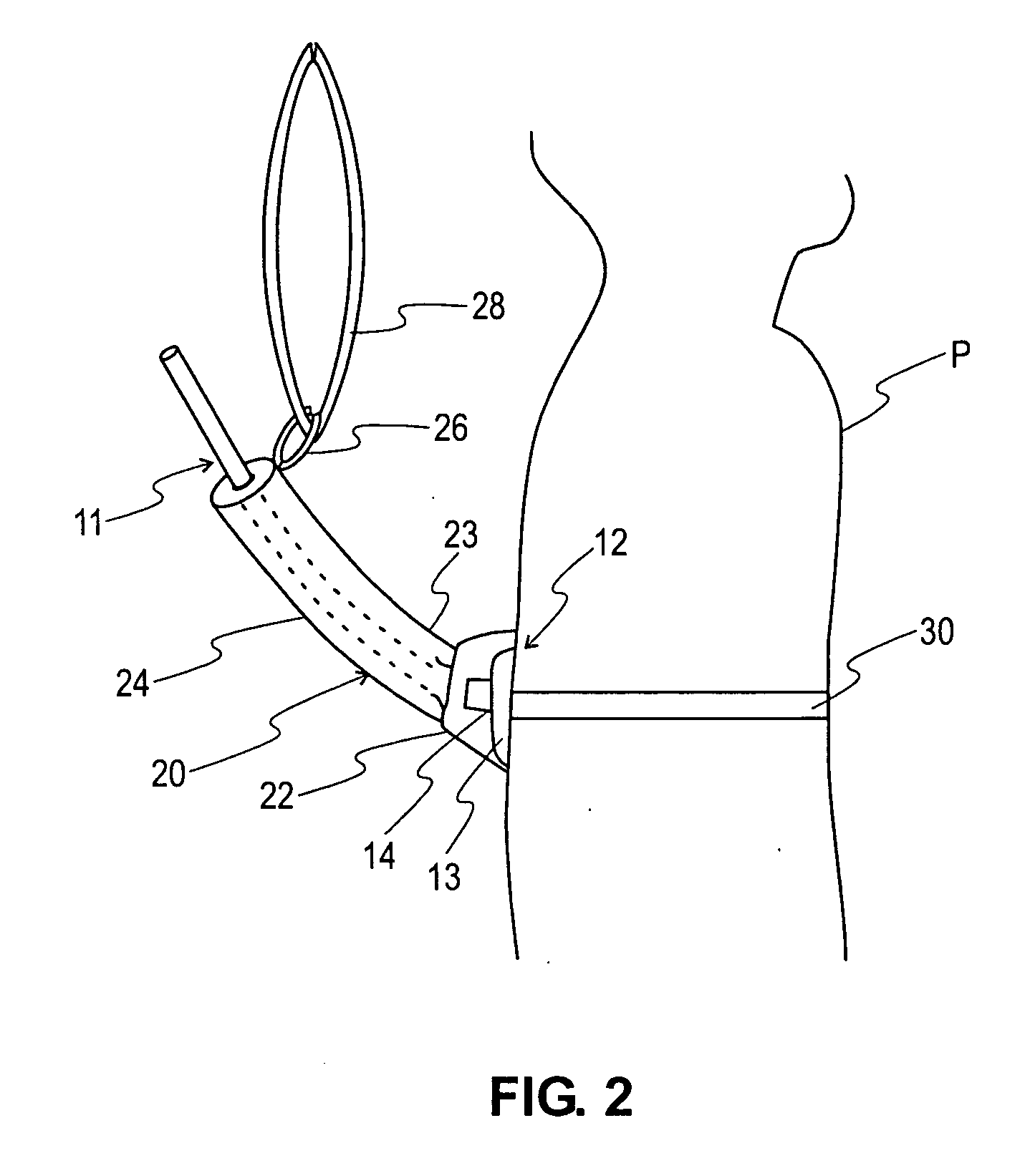
[0024] Turning to FIGS. 2-4, a first embodiment of a g-tube retention device 20 of the present invention is shown. The g-tube retainer 20 comprises a patient base 22, an elongate venting tube extension cover 24 and a transition section 23 interposing and connecting the patient base 22 and venting tube extension cover 24. The patient base 22, transition section 23 and extension cover 24 are integrally formed a...


PUM


Abstract

A gastrostomy tube retainer comprising a patient base, a venting tube extension cover connected to the patient base, and a torso wrap connected to the patient base. The patient base and venting tube extension cover protectively surround the retention button and venting tube extension of surgically implanted gastrostomy tube and are secured to the gastrostomy tube recipient by the torso wrap. In operation, the gastrostomy tube retainer tends to inhibit the non-prescribed removal of the gastrostomy tube by the tube recipient.

Description

[0001] This application is a continuation application of co-pending U.S. Ser. No. 09 / 991,233 filed on Nov. 16, 2001, all of which is fully incorporated herein by reference.FIELD OF INVENTION [0002] The present invention relates to gastrostomy tubes and, more particularly, to a gastrostomy tube retention device that inhibits non-prescribed removal of the gastrostomy tube by the patient. BACKGROUND OF THE INVENTION [0003] A gastrostomy tube, commonly referred to as a “g-tube”, is a tubular device that is placed in the stomach of a patient to provide the patient with essential nutrients for survival. A typical post-surgery g-tube includes a primary tube, a balloon device, a retention button, and a venting tube extension. The primary tube is placed within the stomach through a passageway cut through the abdominal and stomach walls. The balloon device inflates about the periphery of the primary tube in the stomach to anchor the primary tube in position within the stomach. The retention b...

Claims


Application Information

Patent Timeline
Patent Type & Authority Applications(United States)
IPC IPC(8): A61J15/00
CPCA61J15/0015A61J15/0096A61J15/0061
Inventor ENROTH, LORANA A. M.
Owner ENROTH LORANA A M
Why Eureka
Try Eureka