Hinged joint system

a technology of a hippocampus and a joint is applied in the field of hippocampus, which can solve the problems of not controlling movement and not controlling movement, and achieve the effect of reducing the amount of surgical time devoted

Active Publication Date: 2005-05-19
SMITH & NEPHEW INC
View PDF11 Cites 160 Cited by
  • Summary
  • Abstract
  • Description
  • Claims
  • Application Information

AI Technical Summary

Benefits of technology

[0019] A method for replacing a joint with a prosthetic system according to one embodiment of the invention includes resecting the proximal end of the patient's tibia to expose the tibial intramedullary canal of the tibia, resecting the distal end of the patient's femur to expose the femoral intramedullary canal, connecting a tibial stem and a femoral stem to a prosthetic system, the prosthetic system having a mechanical linkage component, inserting the tibial stem into the tibial intramedullary canal, and inserting the femoral stem into the femoral intramedullary canal. The method allows a surgeon to convert to the prosthetic system from a primary or revision prosthesis with common bone cuts and instrumentation. The prosthetic system allows the surgeon to select an appropriately sized tibial insert and a cap so that a pre-assembled femoral component can be used, thereby significantly reducing the amount of surgical time devoted to assembly of the knee.
[0020] Another feature of the present invention is that a bioresorbable bumper can be placed in the prosthetic system to prevent rotation of the prosthetic components around a superior-inferior axis until the bumper is resorbed by the body.

Problems solved by technology

The prior art that allows movement of the axis of rotation or axle allows the axle to move in the anterior and posterior directions, but does not control the movement.
This prior art allows the femoral component and femur to move in the anterior and posterior directions relative to the tibia, but does not control the movement.

Method used


Image

  • Hinged joint system
  • Hinged joint system
  • Hinged joint system

Examples


Embodiment Construction

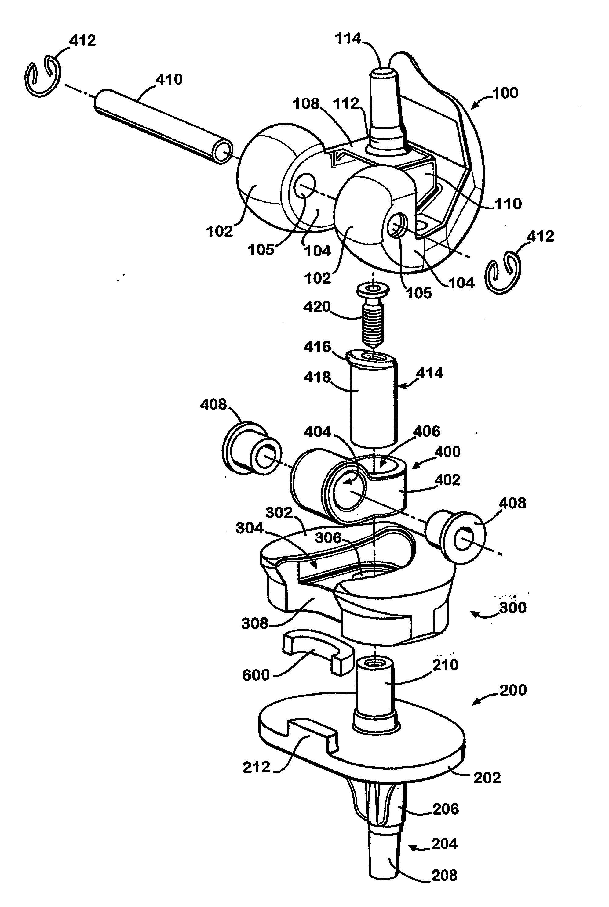
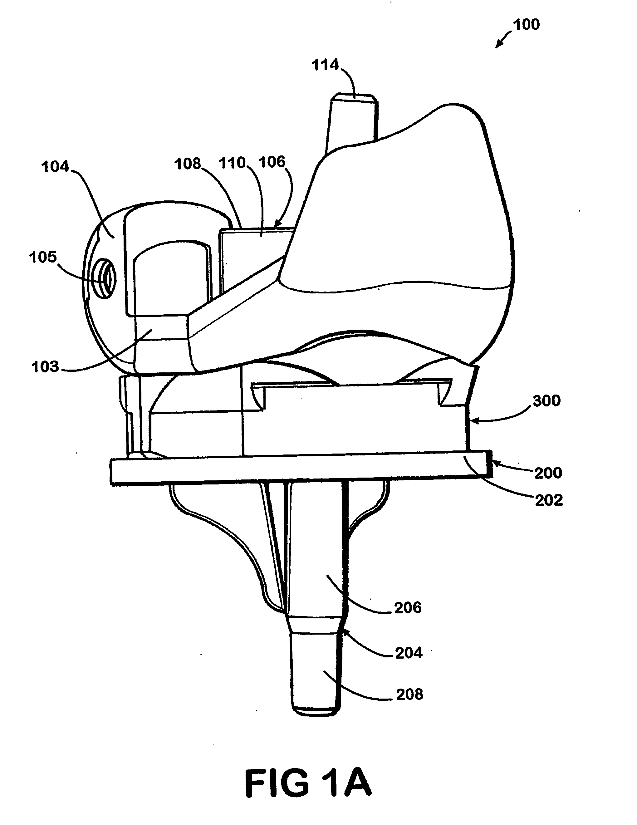
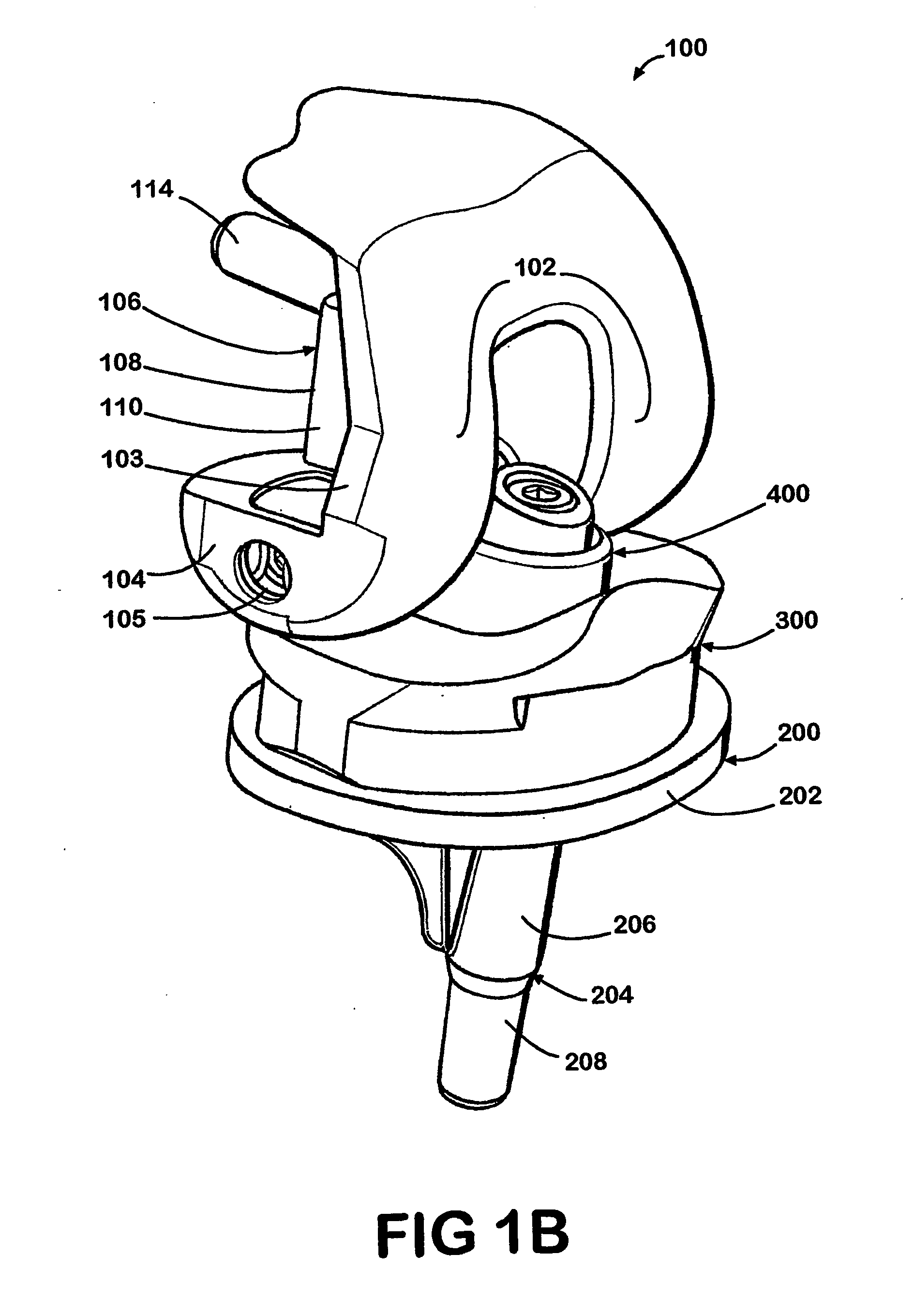
[0028]FIG. 1 illustrates a perspective view of an embodiment of a prosthetic system in extension in FIG. 1A and at 90° flexion in FIG. 1B. FIGS. 2 and 3 show a posterior view and an anterior view, respectively, of an embodiment of the prosthetic system in extension. FIG. 4 shows a top view of an embodiment of the prosthetic system in extension. While the illustrated embodiment is a knee joint, the present invention could be used in other joints, such as a hip joint or a shoulder joint. The prosthetic system includes a femoral component 100, a tibial component 200, a tibial insert 300, and a mechanical linkage component or hinge portion 400. In surgery with the prosthetic system, the tibia and femur are recessed with the intramedullary canals of the tibia and the femur surgically prepared to receive stems. The present invention requires the same bone cuts and instrumentation as a primary or revision system, such as, for example, the Genesis II total knee system from Smith & Nephew, O...


PUM

PropertyMeasurementUnit
timeaaaaaaaaaa
diameteraaaaaaaaaa
rotationaaaaaaaaaa

Abstract

Methods, systems, and devices for replacement of a joint with a prosthetic system that replicates the natural kinematics of the joint is disclosed. A prosthetic system according to one embodiment includes a tibial component having a tibial plateau and a tibial stem portion, the tibial plateau having a top side and a bottom side, a tibial insert, with a bearing surface, adapted to be positioned on the top side of the tibial plateau, a femoral component having a base portion and a central housing, the femoral component having an axis of extension-flexion rotation, the base portion having a pair of condyles, a mechanical linkage component linking the tibial component with the femoral component and with the tibial insert in between the tibial component and the femoral component, so that there is a center of contact between the condyles and the bearing surface, the mechanical linkage component adapted to allow the center of contact to move posteriorly during flexion, provide for the movement of the axis of extension-flexion rotation in the superior-inferior direction, and allow rotation of the tibial component, the bearing surface, and the femoral component about a superior-inferior axis in order to provide and control the natural kinematics of the knee joint.

Description

RELATED APPLICATIONS [0001] This application claims priority to U.S. Provisional Application No. 60 / 342,350 filed Dec. 21, 2001 entitled, “Hinged Knee System,” which is incorporated by reference herein.FIELD OF THE INVENTION [0002] The present invention relates to prosthetic joints, and more particularly to a hinged joint that allows for the natural kinematics of the joint. BACKGROUND OF THE INVENTION [0003] In primary knee joint replacement surgery, a surgeon typically affixes two prosthetic components to the patient's bone structure; a first to the patient's femur and a second to the patient's tibia. These components are typically known as the femoral component and the tibial component respectively. In a typical primary knee joint replacement surgery the ligaments and tendons are sufficiently intact to control the movement of the knee. [0004] The femoral component is placed on a patient's distal femur after appropriate resection of the femur. The femoral component is usually metal...

Claims


Application Information

Patent Timeline
Patent Type & Authority Applications(United States)
IPC IPC(8): A61B17/16A61F2/00A61F2/02A61F2/30A61F2/38A61F2/46
CPCA61B17/1659A61F2/3845A61F2/3854A61F2/3868A61F2/4684A61F2002/30062A61F2002/30131A61F2002/30332A61F2002/30433A61F2002/30497A61F2002/30563A61F2002/30604A61F2002/30878A61F2002/30884A61F2210/0004A61F2220/0025A61F2220/0033A61F2220/0041A61F2230/0013A61F2/385A61F2002/30495A61F2002/30032A61F2/30744A61F2/3859A61F2/389
Inventor CRABTREE, PAULMARIK, GREGSALEHI, ABRAHAMWEAVER, KEVINLANGLAIS, FRANTZHUTEN, DENISHARRISON, DENNIS
Owner SMITH & NEPHEW INC
Why Eureka
Try Eureka