
Gate assembly for tufting machine

a technology of tufting machine and assembly, which is applied in the direction of embroidering machine, sewing apparatus, textiles and paper, etc., can solve the problems of gate malfunction, wear, fatigue, etc., and achieve the effect of sufficient rigidity

Active Publication Date: 2005-05-26
CARD MONROE
View PDF48 Cites 28 Cited by
  • Summary
  • Abstract
  • Description
  • Claims
  • Application Information

AI Technical Summary

Benefits of technology

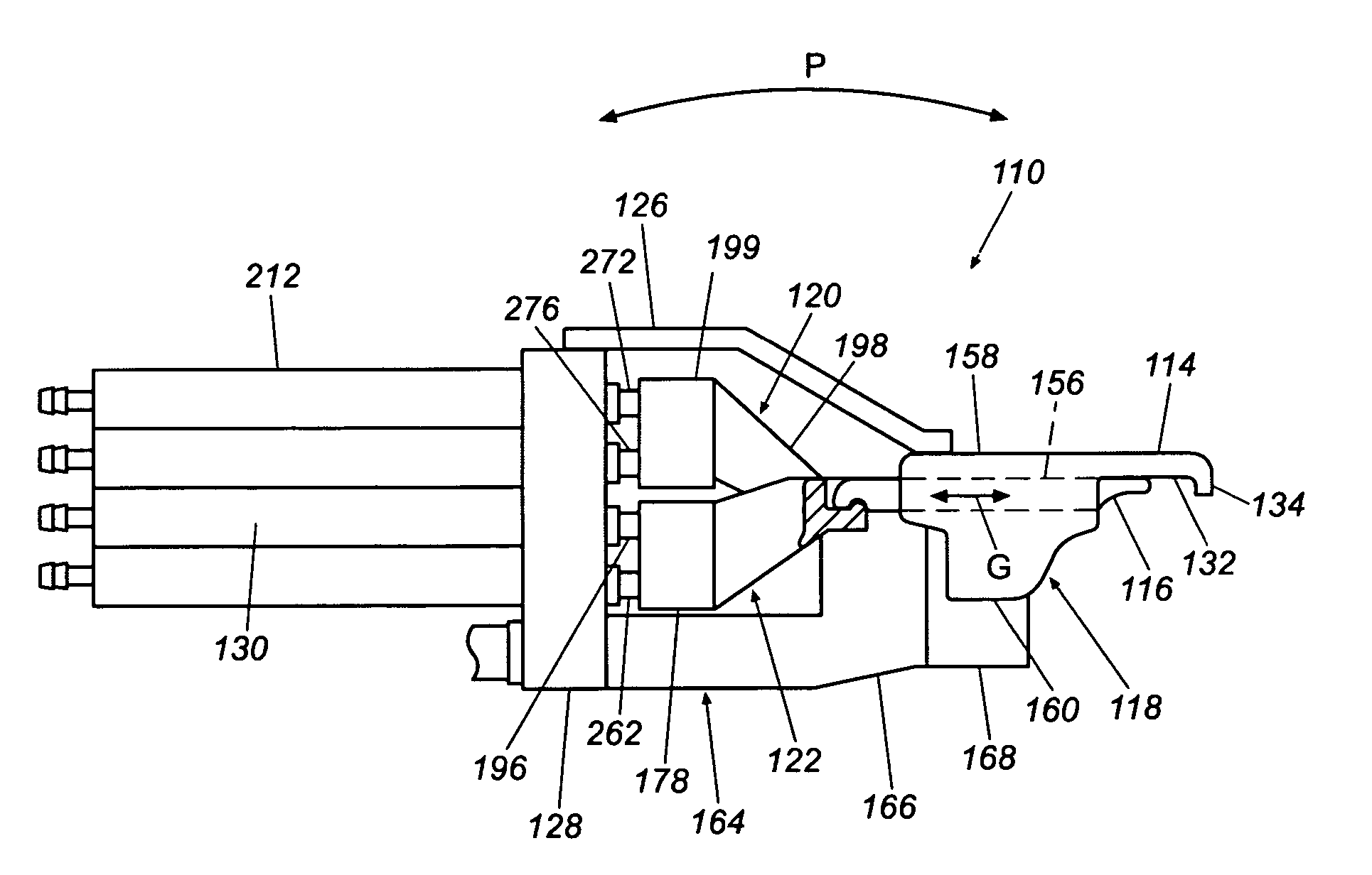
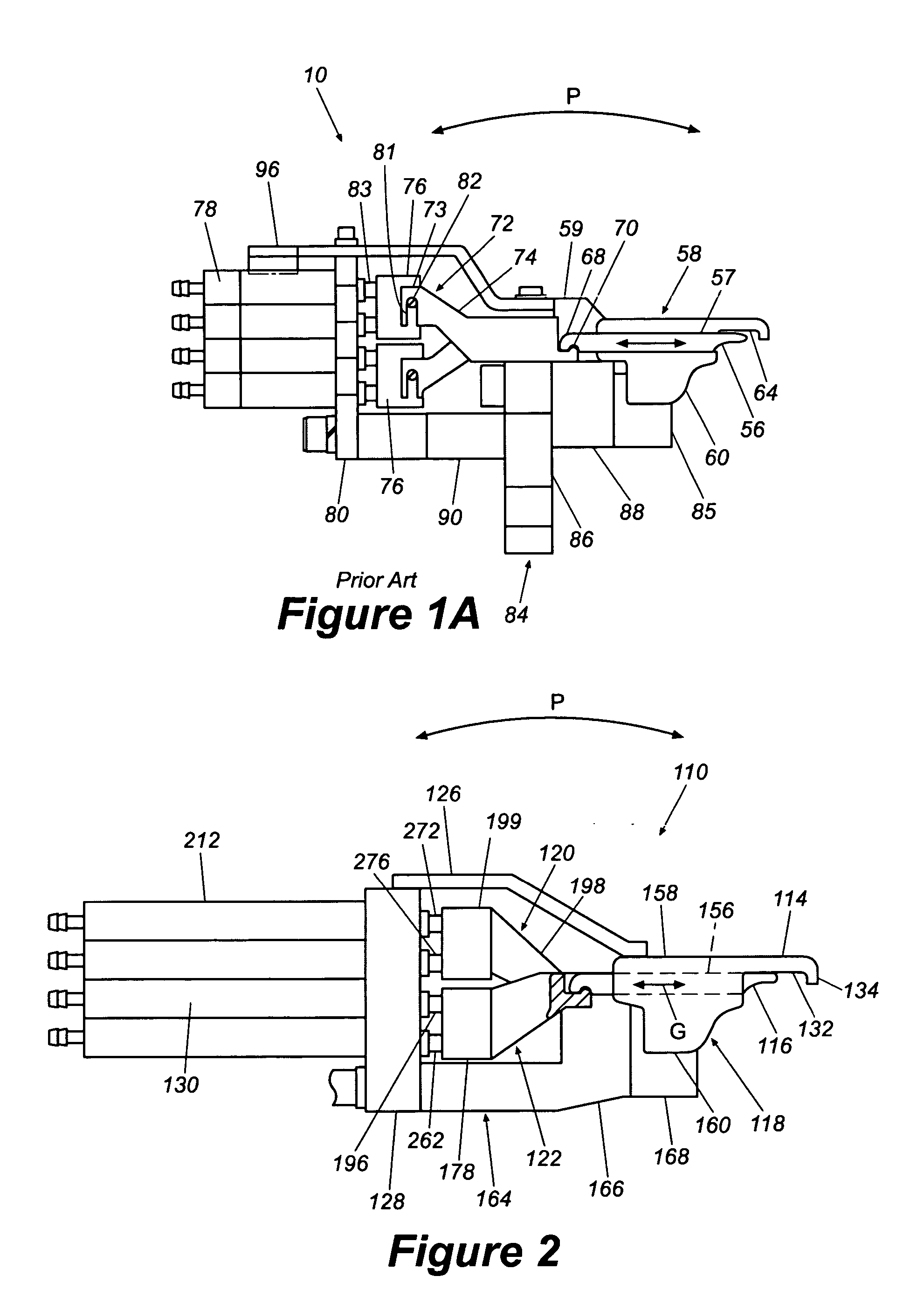
[0011] In another embodiment, a hook mounting arrangement for a tufting machine comprises a hook block rigidly that supports at least first and second hooks and slidably supports at least first and second gates adjacent to the respective first and second hooks. An actuator block supports at least first and second actuators disposed respectively in first and second vertically offset rows. A first connector comprises a first actuator connector portion connected to an output shaft of the first actuator, a first extension portion extends upwardly from the first actuator connector portion and a first gate connector slot extending from the first extension portion. A second connector comprises a second actuator connector portion connected to an output shaft of the second actuator, a second extension portion extends vertically downwardly from the second actuator connector portion and a second gate connector slot extending from the second extension portion. The first and second actuators are configured to reciprocally drive the first and second connectors in an axial direction, wherein the first and second actuator connector portions are respectively connected to the output shafts of the first and second actuators with sufficient rigidity to prevent rotation of the first and second connectors about a generally horizontal axis.

Problems solved by technology

Due to the actuation of the pneumatic cylinders, connectors and the gates are particular vulnerable to wear, fatigue, and malfunctions.
For example, the connector and the gate may become uncoupled resulting in malfunctioning of the gate.
If the gate malfunctions by not properly extending, the pile loop will not be released from the hook resulting in the production of flawed fabric.

Method used


Image

  • Gate assembly for tufting machine
  • Gate assembly for tufting machine
  • Gate assembly for tufting machine

Examples


Embodiment Construction

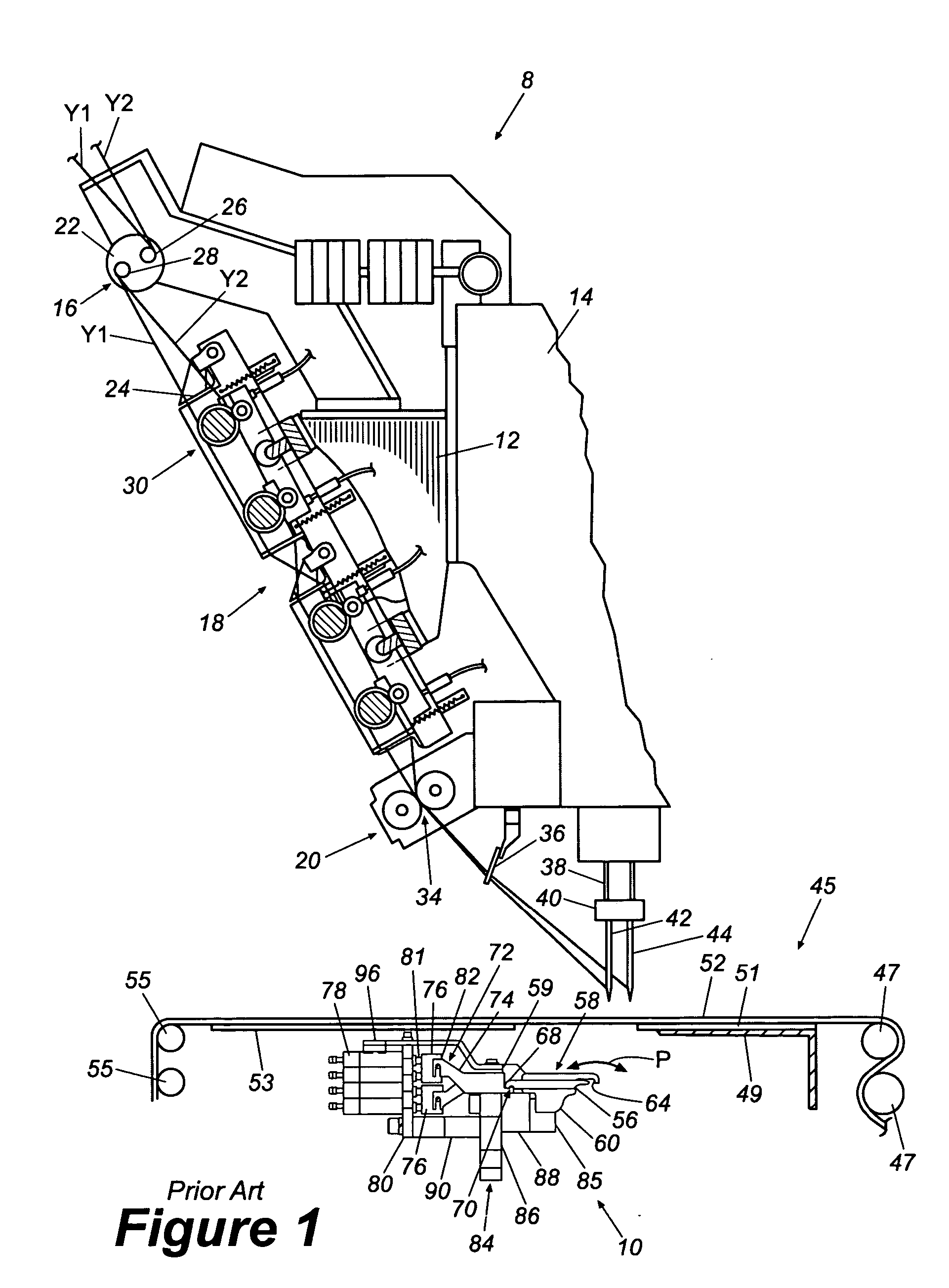
[0027] With reference to FIG. 1, an overall configuration of a known tufting machine 8 with a hook apparatus 10 is described to assist the readers understanding of a preferred environment of use of the present inventions. The tufting machine 8 is described in reference to a coordinate system wherein a longitudinal dimension of the machine 8 extends in a direction generally horizontally and transversely to the direction through which yarn is fed through the machine 8. In addition, relative heights are expressed as elevations in reference to the undersurface of the machine 8.

[0028] Generally, the machine 8 includes a frame assembly 12, a needle head assembly 14, a yarn inlet 16, a yarn feed assembly 18, and a yarn outlet assembly 20. In the illustrated machine 8, the inlet 16, yarn feed assembly 18, and the outlet 20 define a scroll attachment of the tufting machine 8. The head 14, inlet 16, feed assembly 18, and the outlet 20 are supported by the frame 12. The frame 12 includes a nu...


PUM


Abstract

A tufting machine includes a hook apparatus, which has gates and hooks. The hook apparatus has connectors that are coupled to the gates and actuators. The actuators can be actuated to move both the connectors and gates.

Description

CROSS-REFERENCE TO RELATED APPLICATIONS [0001] This application claims priority to U.S. Provisional Application Ser. No. 60 / 525,761, filed Nov. 26, 2003.BACKGROUND OF THE INVENTION [0002] 1. Field of the Invention [0003] The present invention is related to a tufting machine, and more particularly, an improved gate assembly for a tufting machine. [0004] 2. Description of the Related Art [0005] Tufting machines are widely used for manufacturing tufted pile fabrics, such as carpeting. Many such tufting machines include hook and gate mechanisms for creating loops. [0006] Tufting machines have a plurality of yarn carrying needles. During operation the portions of the needles carrying the yarn pass though a heavy fabric to form loops of yarn below the fabric. The hook mechanism has loopers or hooks that are located below the fabric and are oscillated to capture loops of yarn so that when the needles are withdrawn from the fabric, the loop is held below the fabric to form loop pile. Many t...

Claims


Application Information

Patent Timeline
IPC IPC(8): D05C15/20D05C15/22D05C15/24
CPCD05C15/20D05D2207/02D05C15/24D05C15/22
Inventor JOHNSTON, KENDALL
Owner CARD MONROE
Learn More