Display unit having a center display

a display unit and center display technology, applied in the field of display units, can solve the problems of reducing the appearance and design quality of the display unit, and achieve the effect of improving the design quality

Active Publication Date: 2005-05-26
YAZAKI CORP
View PDF13 Cites 45 Cited by
  • Summary
  • Abstract
  • Description
  • Claims
  • Application Information

AI Technical Summary

Benefits of technology

[0017] According to the above, a front end of the pointer can indicate graduations on the dial positioned in front of the display without a slot provided on the dial. Therefore, the display attains high design quality.
[0021] According to the above, even when the drive is positioned at the backside of the display, the front end of the pointer can indicate the graduations on the dial positioned in front of the display without a slot provided on the dial. Therefore, the display attains high design quality.
[0024] According to above, in front view, since this overlapping part of the pointer, overlapping with the display is seen as a part of the display and not as a part of the pointer, the pointer is seen as being rotatable only in front of the display. Therefore, the display attains higher design quality.
[0027] According to above, in front view, since this overlapping part of the display, overlapping with the dial is seen as a part of the dial and not as a part of the display, the pointer is seen as being rotatable only in front of the display. Therefore, the display attains higher design quality.

Problems solved by technology

However, in cases where the dial indicates important information such as vehicle speed and the display displays relatively unimportant information such as the present time, there is a demand to improve visibility of the dial by arranging the dial in front of the display.
However, in the conventional display unit described above, there is a problem in that the slot 12b should be provided on the dial 12, and reduces an appearance and design quality of the display unit.

Method used


Image

  • Display unit having a center display
  • Display unit having a center display
  • Display unit having a center display

Examples


first embodiment

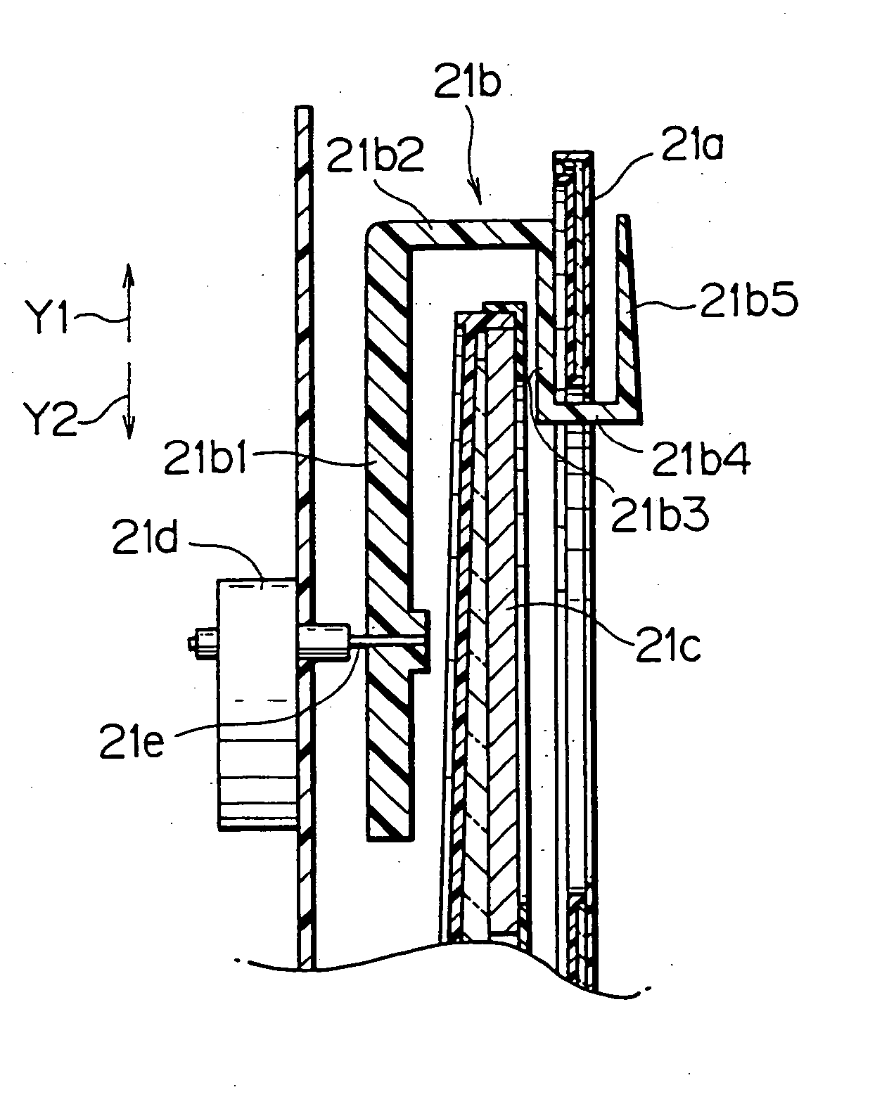
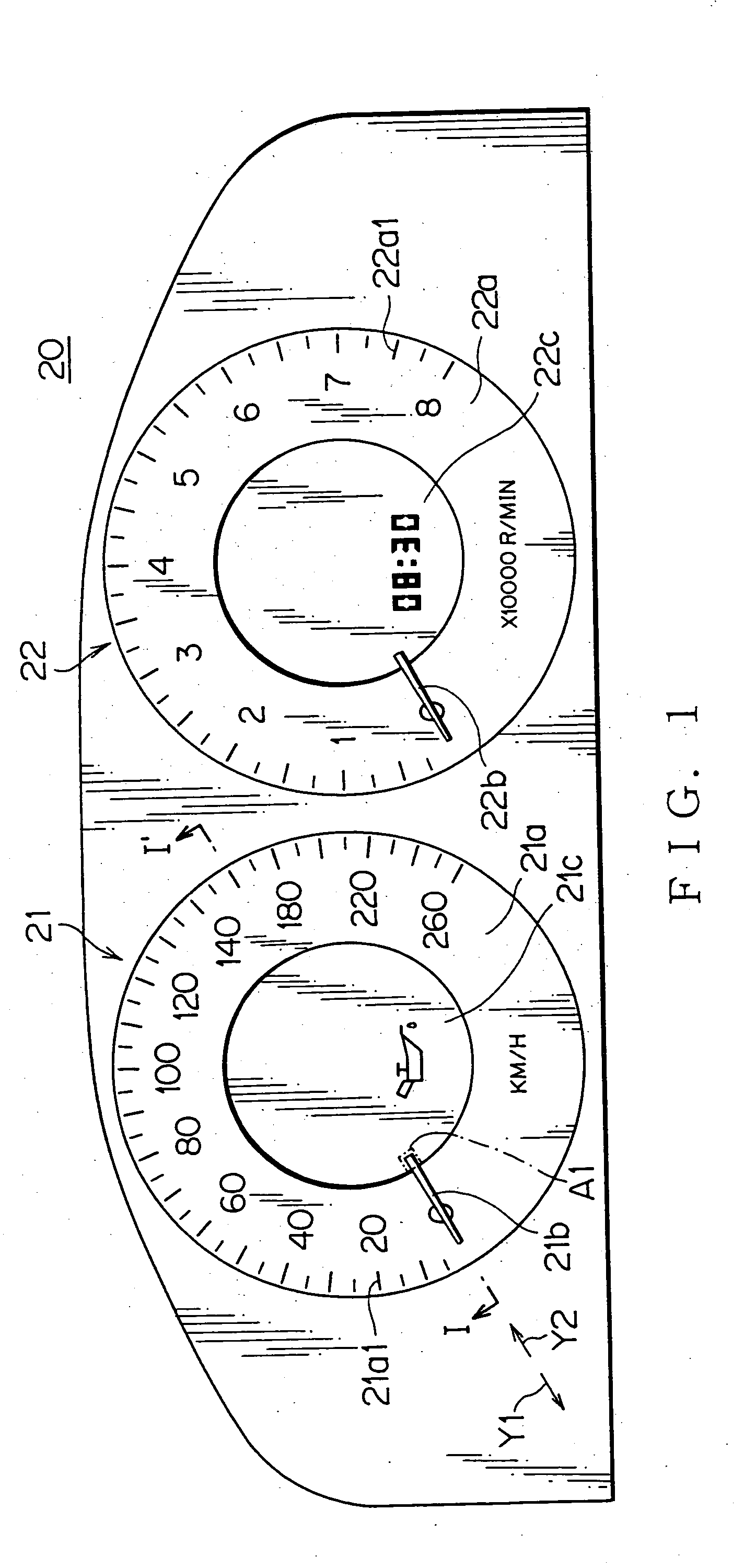
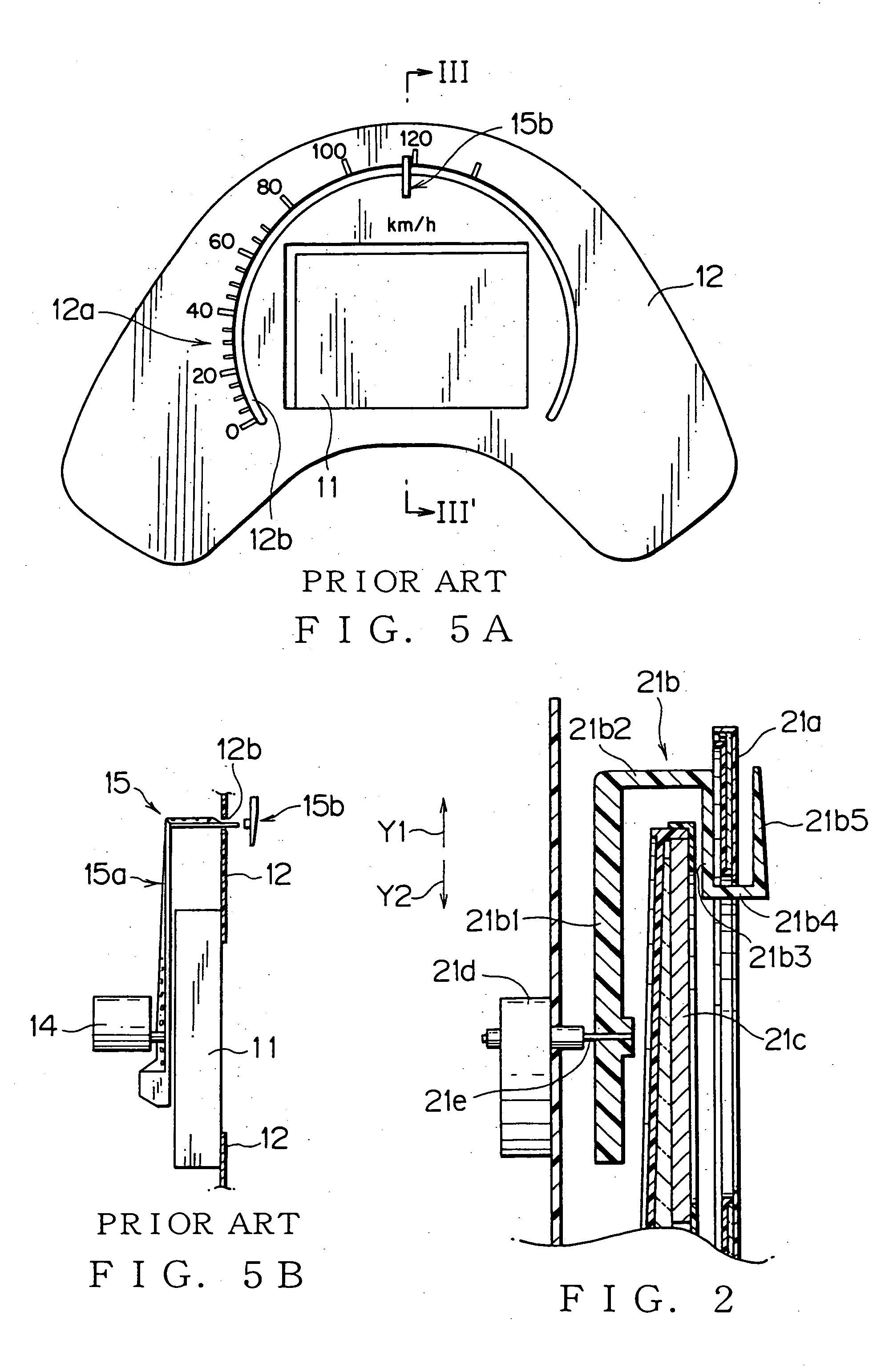
[0035] A first embodiment of display units of this invention will be explained with reference to FIGS. 1 to 2. FIG. 1 is a front view showing an embodiment of a combination meter 20 equipped with display units of this invention. FIG. 2 shows a cross-sectional view taken on line I-I′ of the combination meter 20 in FIG. 1. As shown in FIG. 1, the display units of this invention is, for example, mounted on the combination meter 20 of a vehicle. The combination meter 20 includes a speedometer 21 and a tachometer 22, as the display units.

[0036] As shown in FIG. 1, the speedometer 21 is configured with a dial 21a, a pointer 21b, and a liquid crystal display (LCD) 21c. The dial 21a is formed in a doughnut-like shape in front view, having a substantially circular hole in a middle thereof. Graduations 21a1 are formed along an outer periphery of the dial 21a. The LCD 21c is positioned at a backside of the dial 21a, and can be seen in front view via the hole surrounded by the dial 21a. Namely...

second embodiment

[0049] In order to improve an appearance of the display unit, as shown in FIG. 3, according to a second embodiment of this invention, color of the projecting end A1 of the pointer 21b, overlapping with the LCD 21c, may be set to identical with, or similar to the color of the LCD 21c. For example, when the colors of the dial 21a, the LCD 21c, and the pointer 21b are respectively white, dark color, and blue, the color of A1 of the pointer 21b is set to the dark color (the same color as that of the LCD 21c), and the color of an overlapping part A2, overlapping with the dial 21a, is set to blue. Thereby, the projecting end A1 of the pointer 21b is not seen as a part of the pointer 21b in front view, and is seen as a part of the LCD 21c. Therefore, the pointer 21b is seen as only being rotatable on a front surface of the dial 21a, and the design quality of the display unit is improved.

third embodiment

[0050] Alternatively, as shown in FIG. 4, in front view, an overlapping part of the LCD 21c, overlapping with the pointer 21b, may be set to identical with, or similar to the color of the dial 21a. Specifically, when the colors of the dial 21a, the LCD 21c, and the pointer 21b are respectively white, dark color, and blue, the color of an overlapping part A3 of the LCD 21c is set to white (the same color as that of the dial 21a). Thereby, the overlapping part A3 of the LCD 21c is not seen as a part of the LCD 21c in front view, and is seen as a part of the dial 21a. Therefore, the pointer 21b is seen as only being rotatable on a front surface of the dial 21a, and the design quality of the display unit is improved. Further, if the overlapping part A3 of the LCD 21c is made of the same material as that of the dial 21a, the overlapping part will be seen as the part of the dial 21a more naturally.

[0051] The same configuration in the dial 21a is applied to the dial 22a and therefore expl...


PUM


Abstract

A dial 21a is positioned in front of an LCD 21c, and has an inner periphery surrounding the LCD 21c. A pointer 21b is rotatable by a drive 21d positioned at a backside of the LCD 21c. The pointer 21b is extended from a rotation center in a direction Y1 against the rotation center along a back surface of the LCD 21c, then bent and extended along an outer periphery of the LCD 21c, and bent and extended in the direction Y2 toward the rotation center via a gap formed between a front surface of the display 21c and a back surface of the dial 21a. Then, the pointer 21b is extended along an inner periphery of the dial 21a, and bent and extended in the direction Y1 along a front surface of the dial 21a.

Description

BACKGROUND OF THE INVENTION [0001] The priority application Number Japanese Patent Application 2003-393819 upon which this patent application is based is hereby incorporated by reference. [0002] 1. Field of the Invention [0003] This invention relates to a display unit having a display such as an LCD at the center of a dial of a revolution indicator such as a tachometer or a speedometer. [0004] 2. Description of the Related Art [0005] As a display unit described above, for example, it is known that a display is arranged in front of a dial of a normal revolution indicator. This arrangement prevents a pointer from obstructing a view of the display, so that the display may be arranged in the center of the dial. [0006] However, in cases where the dial indicates important information such as vehicle speed and the display displays relatively unimportant information such as the present time, there is a demand to improve visibility of the dial by arranging the dial in front of the display. [...

Claims


Application Information

Patent Timeline
Patent Type & Authority Applications(United States)
IPC IPC(8): B60K37/02B60R11/02G01D7/00G01D13/22G09F9/35
CPCB60K37/02B60K2350/1064Y10S116/36G01D13/22Y10S116/06G01D7/002B60K2370/154B60K2370/698B60K2370/336B60K2370/6985
Inventor TANAKA, MITSUTOSHIKOMURA, KENGO
Owner YAZAKI CORP
Why Eureka
Try Eureka